If you were into car audio in the ’90s, you’ve likely heard of amplifiers having mixed-mode or tri-mode capability. The implication was that these amps could power a pair of coaxial speakers and a subwoofer at the same time from a cost-effective and straightforward two-channel design. If you dig down into the nitty-gritty of how this works, you’ll see it’s pretty simple. With that said, the concept has some drawbacks in terms of system configuration and calibration options. So let’s dive into an exploration of car audio amplifiers with tri-mode capability.
Part One – Amplifier Output Design
Most stereo car audio amplifiers can be wired in a configuration called bridging such that they can power a subwoofer. You can use the amp to drive a set of speakers, or your installer can wire it to power a single high-power subwoofer. If the amp has a large enough power supply (something many don’t these days), it should produce almost four times the 4-ohms-per-channel power rating into the sub. For example, an amp that produces 100 watts per channel into 4 ohms should make close to 400 watts when the two channels are bridged to a single 4-ohm subwoofer.
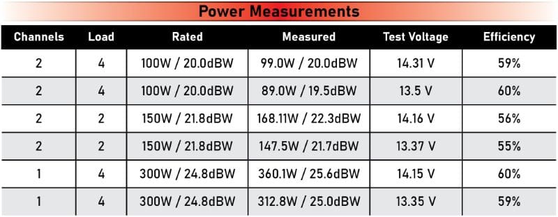
The chart above shows that the Rockford Fosgate P300X2 I tested a while back produces 360 watts into a 4-ohm load in a bridged configuration and 99 watts per channel when driving a single 4-ohm load on each output. This performance is outstanding in an era where amplifiers are designed based on size rather than having a power supply capable of delivering enough current to the load at low impedances.
Let’s review how the signals in the amp are configured such that they can provide more power to a bridged load. In these amps, one terminal on each speaker output is usually referenced to the ground, and the other terminal passes the amplified audio signal.
In the example below, the left positive and right negative terminals don’t produce any voltage. The signal on the left negative is inverted compared with what comes out of the right positive.
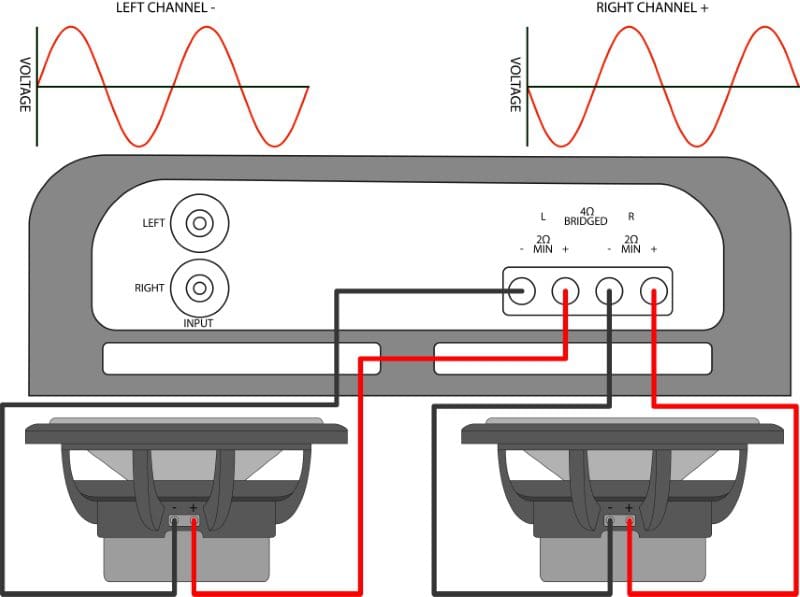
Though initially counterintuitive, the result is that both speakers move forward and rearward at the same time when identical signals are sent to each input terminal. The inverted left channel signal is compensated for by the wiring of the speaker. Rather than having a positive signal on the positive terminal to push the speaker forward (for example), it has a negative signal on the negative terminal that produces the same speaker cone motion.
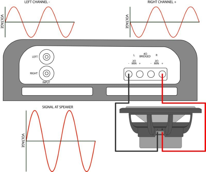
The amplifier can also be wired in a bridged configuration using the left negative and right positive terminals. Given that the audio signal on each of these connections is opposite in polarity, the amplifier produces twice as much voltage across the load (speaker) and, theoretically, four times as much power.
Part Two – Passive Crossovers
The concept of tri-mode or mixed-mode amplifier wiring involves wiring a pair of speakers in stereo and a subwoofer in a bridged configuration at the same time on a single amplifier.
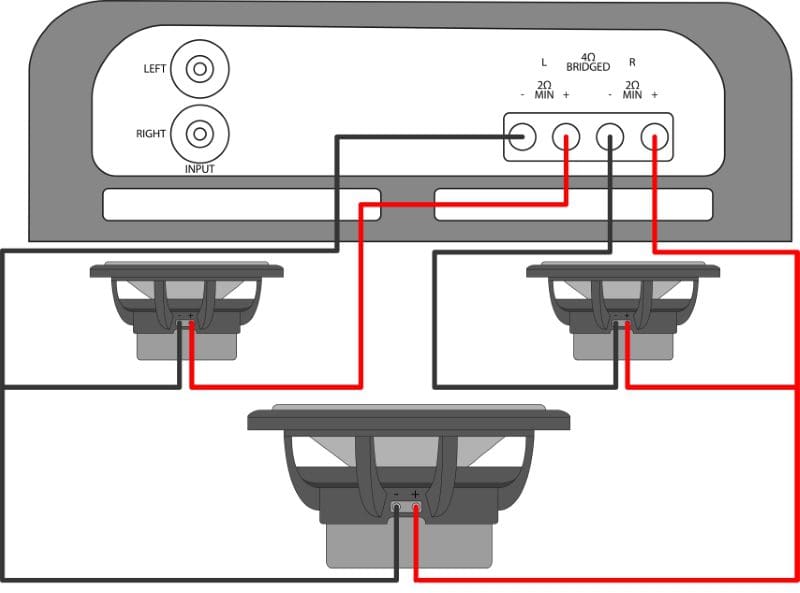
The problem with the above wiring configuration is that the amplifier will see a very low-impedance load. The bridged 4-ohm woofer presents a 2-ohm load to each channel. The stereo speakers present a 4-ohm load to each channel. The result is that the amp will attempt to deliver adequate current to drive this 1.33-ohms net load per channel. Chances are, it won’t be happy and will overheat quickly.
The second problem is that the same signal goes to all the speakers. The amp will send low-frequency information to the smaller stereo speakers and both midrange and high-frequency information to the subwoofer. We want differently sized speakers to operate within the range of frequencies they were designed for. So, to filter the signals, we would add passive crossover components. You can read about how capacitors and inductors work in the recent articles we’ve posted.
For this example, we’ll choose capacitor values to protect the smaller speakers from producing too much bass. A value of 200 microfarads wired in series with a 4-ohm speaker creates a 199-hertz high-pass filter. Unfortunately, a capacitor is only a first-order filter, so it doesn’t provide a significant amount of low-frequency attenuation. We’ll use a 6.5-millihenry inductor for the woofer to create a low-pass filter with a crossover frequency of 98 hertz. Yes, the crossover points are pretty far apart. This is one of the drawbacks of first-order filters. With that said, thousands of audio systems were installed this way before multichannel amps and systems with active filters became popular. It works satisfactorily.
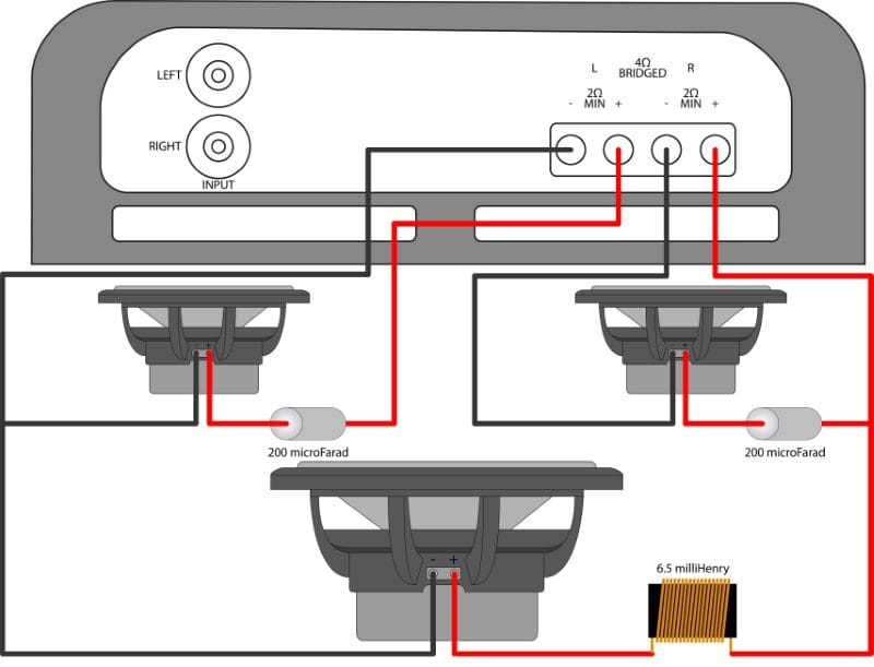
If a stereo amplifier can be bridged like this, it’s 99% likely that it can be wired in a mixed-mode or tri-mode configuration.
Part Three – Why We Don’t Use Tri-Mode Amp Wiring Anymore
To wrap this up, I should explain why we don’t see systems wired like this these days. First, the crossover frequencies are fixed. We can’t quickly increase or decrease the crossover frequency without adding new components. This limitation makes fine-tuning the system expensive and time-consuming.
Second, we can’t adjust the subwoofer’s output relative to the speakers. If there is too much, or more likely, not enough bass, there isn’t much we can do. We could add more subwoofers to the system to increase the amount of bass produced. Two 12-inch subwoofers offer significantly more output per watt than a single 10, for example. So long as the net load on the amp remains 4 ohms, that would work. Once again, that involves redesigning the system, and it comes with significant expense. We could turn up the bass control on the radio, but that also sends more bass to the smaller speakers. This extra bass will have an audibly detrimental effect on their performance.
Lastly, a first-order crossover on the smaller speakers doesn’t offer much low-frequency protection. Yes, there are more complex passive crossover networks that attenuate signals at 12, 18 or 24 dB per octave that would let us use lower crossover points. However, building those networks so they function properly is very expensive. In addition, getting these steeper crossovers to work ideally requires careful driver impedance measurements and component simulation that go well beyond what most software applications and only calculators offer. In short, it’s just not worth spending $50 on inexpensive crossover parts or hundreds on good components when you can choose an amplifier with an additional set of channels that offers complete flexibility for a similar investment.
Once each speaker in the system is on a dedicated amplifier channel, you are instantly ready to add a digital signal processor to the system. The result of proper level setting, signal delay configuration and frequency response calibration will do more for the perceived accuracy of the system than any other single upgrade.
Have Mixed-Mode Applications Gone the Way of the Dodo Bird?
Given the drawbacks of configuring a car audio system that uses mixed-mode or tri-mode wiring configurations, it’s doubtful you will see a professional install this in a vehicle. With that said, if you have a two-channel amp that’s bridgeable and a sub lying around, it might be worth experimenting with this to add a little warmth and impact to your sound system. If you like it, it would sound even better with a dedicated amp for each speaker. Drop by your local specialty mobile enhancement retailer to find out about the subwoofer and multichannel amplifiers available to make your car audio system upgrade sound amazing.
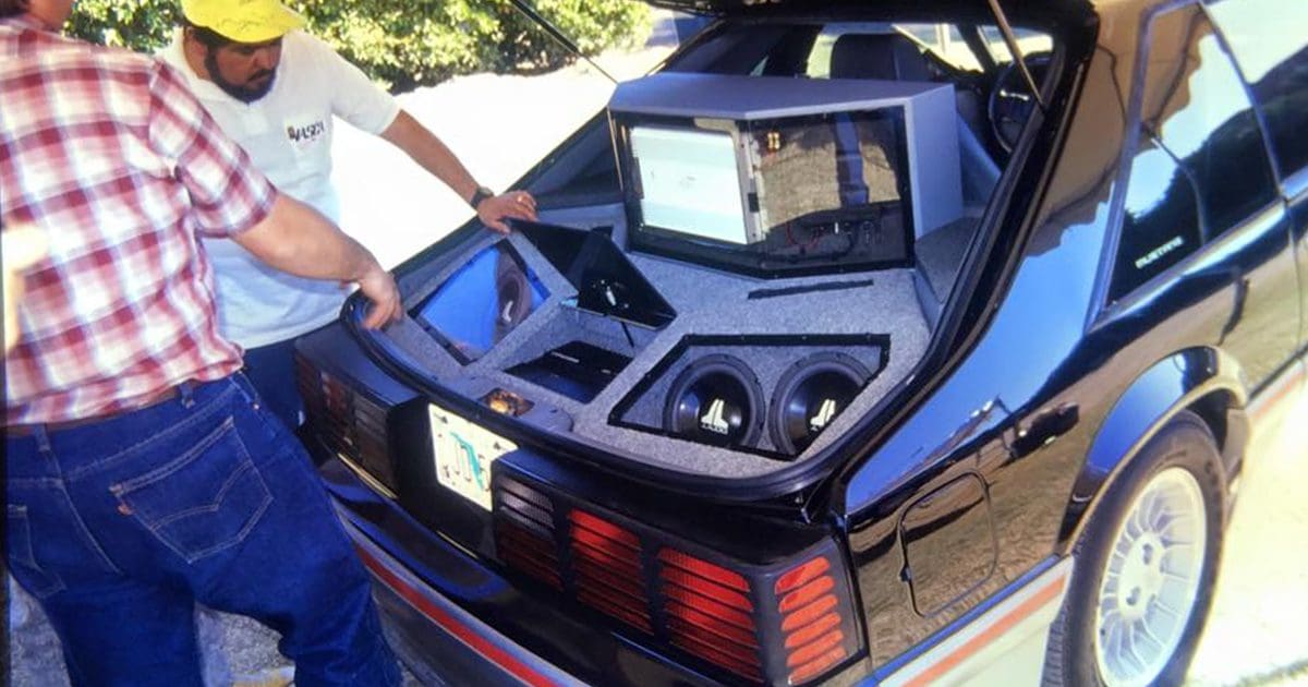
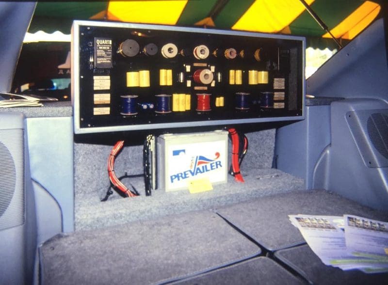
Lead-In Image: Thanks to Manville Smith from JL Audio for providing us with this photo of Lucio Proni’s Ford Mustang from the 1989 IASCA Finals. Proni, a co-founder of JL Audio, won the 1-100 watt Pro class along with the Pro class Best of Show award with a single Precision Power two-channel amp and 25 speakers filtered by capacitors, inductors and resistors. By the way, the L in JL Audio stands for Lucio. The J is for the company’s other co-founder, James Birch.
