Against my better judgment, I recently found myself scanning through posts on several audio subreddits for article ideas. On the same day, in two different groups, I partook of discussions about how speaker technologies have improved over the last few decades. The original posters were claiming that there hadn’t been any significant improvements in years, so paying for premium products was a waste of money. Has the basic design changed? Not really. Have there been improvements? Absolutely! Let’s dive in.
Moving Coil Loudspeakers
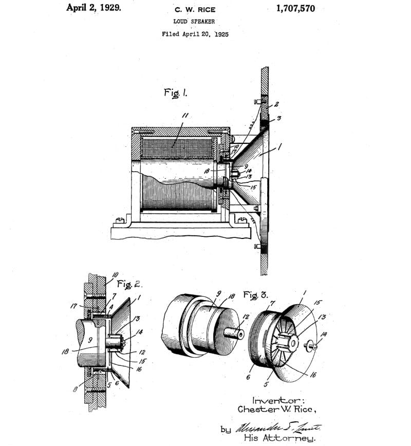
The basic design concept of a moving coil loudspeaker hasn’t really changed since it was introduced in 1925. That’s right; we are only a few years away from the 100th anniversary of the loudspeaker! In the most basic of terms, a moving coil loudspeaker combines a cone with a coil of wire wound around a cylindrical tube on the bottom. This tube is located within a fixed magnet. When alternating current flows through the wire, the changing polarity causes the cone assembly to be pulled down or pushed upward.
As you can imagine, the first speakers would have been somewhat limited in their excursion capabilities and fidelity. Much of the design would have been focused on making the system work as opposed to perfecting its operation.
Speaker Technology Improvements
There are two fundamental problems with loudspeakers: They can be quite non-linear at high excursion levels, resulting in the addition of harmonic and intermodulation distortion. Additionally, resonances in the cone, dust cap and surround can introduce unwanted distortion to the audio signals they produce.
Through the 1950s and ’60s, many engineers and technicians worked on understanding how speakers interacted with enclosures, and those experts began to develop electrical models that could be used to simulate different applications. It wasn’t until the early ’70s that relatively accurate models were available to provide accurate simulations of acoustic suspension (sealed), bass reflex (vented) and passive radiator enclosure designs. Even to this day, these models don’t take into account speaker distortion and do nothing to describe the quality or accuracy of a speaker. As such, two speakers can be modeled in enclosure design software and produce identical response curves, yet the drivers could sound very different in real-world applications because of differences in compliance, motor force, inductance and component resonance.
Likewise, these models don’t take into account changes in speaker parameters as the driver breaks in over the first few dozen hours of playtime or the degradation of rubber or foam surrounds, composite cone materials and softening of suspension components over the life of the driver. Spending too much time thinking about these things will have you wondering how any speaker could ever sound good!
Modern Distortion-Reducing Speaker Technologies
We are going to jump deep into four high-end features that speaker engineers use to improve the linearity of a loudspeaker to reduce its nonlinearity. The first is a shorting ring. These are also commonly referred to as demodulating rings or Faraday rings. These are a cylinder or sleeve of copper or aluminum that is added to the motor assembly just below the top plate. The purpose of this ring is to reduce the effective AC inductance in the voice coil. The result is improved upper midrange response in speakers and improved midbass response in woofers and subwoofers. The rings also reduce changes in inductance between the voice coil being outward from rest and inward to reduce distortion.
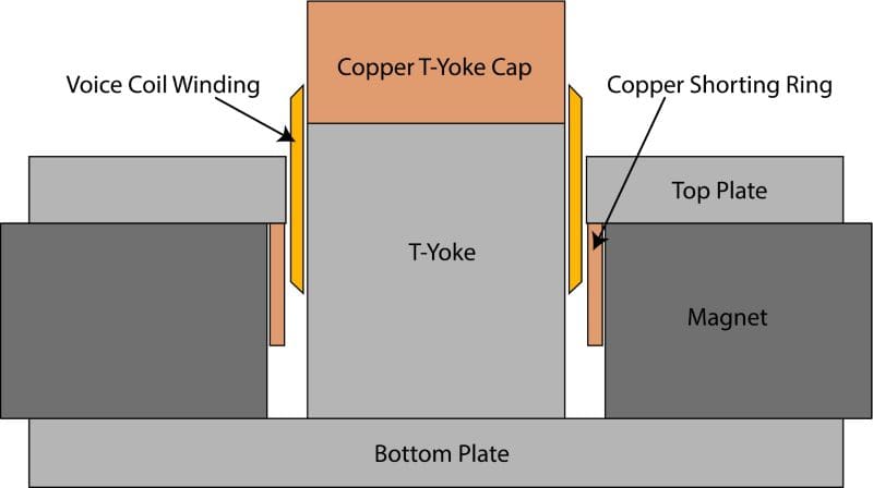
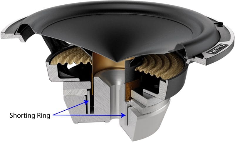
Shorting rings can also be implemented on the pole piece that extends upward inside the voice coil former in the form of a copper or aluminum cap. These serve the same purpose in reducing changes in the inductance and, thereby, reducing distortion.
The graph below shows the difference between a small woofer with and without a shorting ring. As you can see, changes in inductances based on cone position are dramatically reduced. This translates into the frequency response of the driver being more linear over its excursion range.
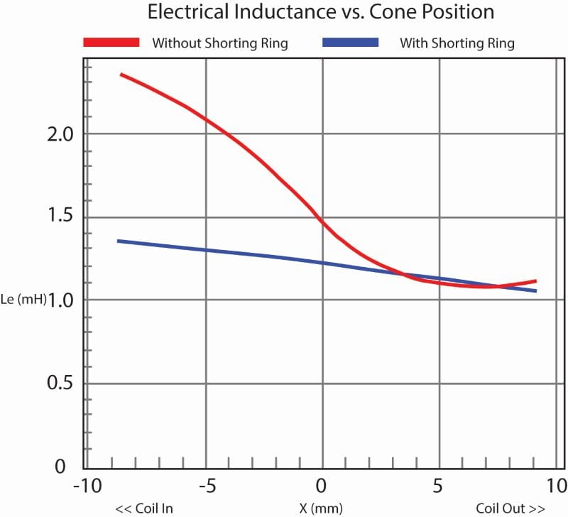
How would one interpret the above graph? Let’s start by considering that inductance in a voice coil affects frequency response by increasing the perceived impedance of a speaker. The formula to calculate inductive reactance is Xc = 2 x π x F x L, where π is 3.14159, F is the frequency in hertz and L is inductance in millihenries. If we look at the graph above when the speaker has moved rearward by 5 millimeters, the driver with the shorting ring will have an inductance value of about 1.3 millihenries, and the driver without will have an inductance of 2.1. At 100 hertz, the difference in impedance is 0.818 ohm for the shorting ring driver and 1.319 ohms for the driver without the inductance management. At 200 hertz, those numbers are 1.634 and 2.639 ohms.
Drivers without this technology effectively “warble” as their high-frequency performance changes when the cone is rearward from rest as opposed to being forward from the rest position.
Shorting rings are not new. I vividly recall installing a set of Rockford Fosgate Pro-124 12-inch subwoofers in a client’s pickup truck in the late 1980s that included shorting rings as a feature.
Top Plate and Voice Coil Geometry Affect Linearity
Another technology that helps to improve linearity is speakers designed with two voice coils stacked one on top of the other or a tall top plate with a groove in the middle. The intent is to produce the same fixed magnetic field force on the motor across its entire movement range.
A little background on motor flux. The flux is the force the magnet in the speaker exerts on the voice coil. If this force changes relative to the position of the voice coil in the gap, the cone won’t move proportionally to the drive signal, and distortion will be added to the output. A perfect speaker would present an equally strong magnetic field to the coil no matter what position it was in. In reality, as the cone moves relatively far forward or rearward, the strength of the field drops off quickly.
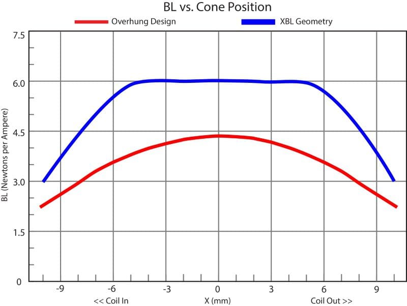
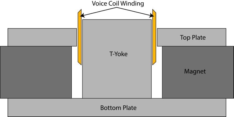
Let’s look at a common voice coil configuration known as an overhung voice coil. In this design, the voice coil winding is much taller than the top plate. As the coil moves inward and outward, there’s a similar amount of coil in the gap. This produces the red curve in the above graph. The output of the driver suffers some because part of the winding is not pushing the cone as it is outside of the top plate and the magnetic field.
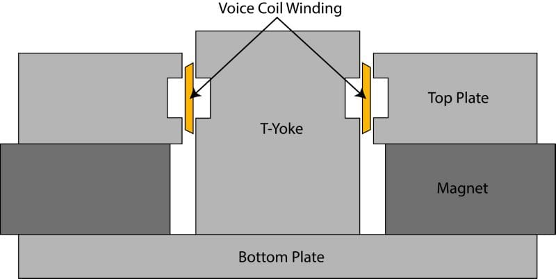
One alternative to overhung voice coil geometry is the XBL configuration created by Dan Wiggins at Acoustic Development International. This design uses an underhung alignment with a large notch in the center of the top plate. The force applied to the voice coil is quite linear over the most commonly used range of the speaker. The images XBL-related images in this article are reproductions of the work done by Mr. Wiggins.
Suspension Compliance Affects Performance
A third consideration is the compliance or stiffness of a speaker’s suspension components. Just as we want the magnetic field force to be equal as the cone moves forward and rearward, and we don’t want any changes in the drivers’ inductance, we will want the force exerted by the suspension components to be linear in both directions. Some high-performance subwoofers use a pair of mirrored spiders to achieve this. The spiders are the same, but one is installed upside down. Where one might be stiffer in one direction, the upside-down unit should have the same stiffness in the opposite direction to make the system more linear. When looking at charts of a driver’s compliance, we measure Kms, or the number of Newtons of force per millimeter of movement. This should be as linear as possible.
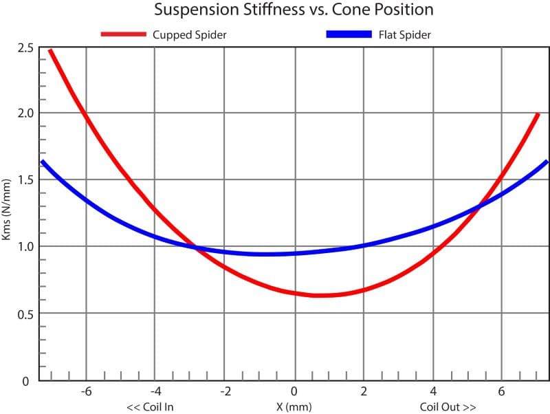
The graph above shows two 6.5-inch woofers. The driver represented by the blue curve has a flat spider. The driver in red has a cupped spider. Cupped spiders exhibit a larger change in compliance of the operating range, and are also more compliant in the outward direction as compared to when they move inward.
Cone Rocking Can Be an Issue
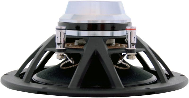
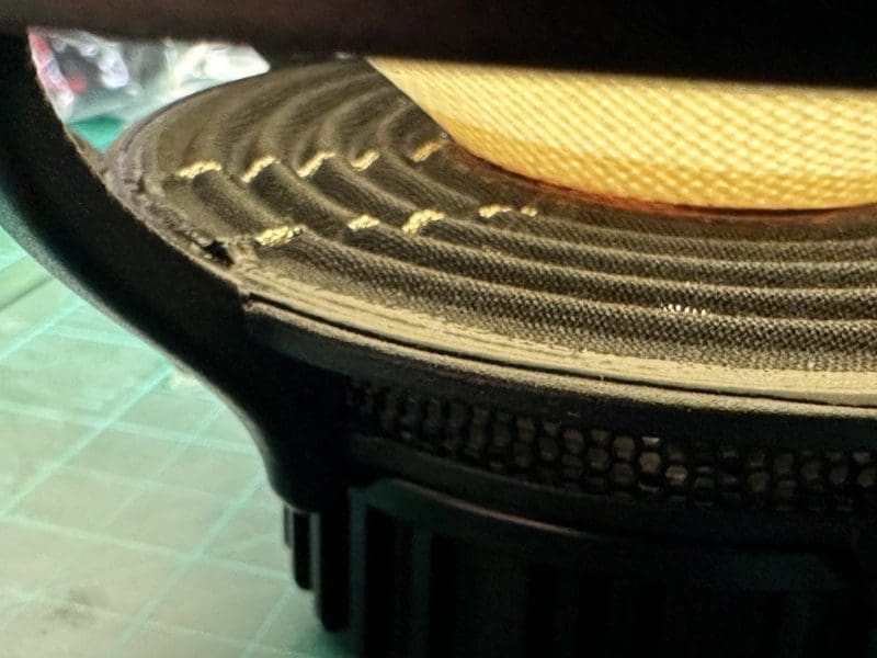
A feature that I have only seen on one driver is a set of mirrored sewn tinsel leads on a single voice coil speaker. The purpose of these leads is to ensure that the compliance of the suspension is equal on both sides of the driver. This reduces the chances of the cone rocking as it moves in and outward. The resulting linear motion allows the manufacturer to design the driver with a tighter voice coil gap and thus increase its efficiency.
Reduce Unwanted Resonances
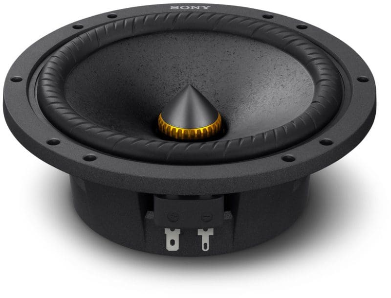
As we mentioned at the beginning of this article, unwanted resonances in components can be a significant issue. The cone itself can resonate, as can the surround and dust cap. In fact, dust caps are notorious for causing unwanted spikes in high-frequency information from woofers and midrange drivers. Taming these issues is all part of designing a high-quality speaker.
Upgrade Your Speakers and Subwoofers
If you’re using drivers without any of the technologies we’ve mentioned here, you may want to consider an upgrade. The improvement in clarity and detail can be phenomenal. Drop by your local specialty mobile enhancement retailer and ask to audition speakers that include the performance-improving features we’ve listed. We know you’ll be impressed by how much speaker technology has improved in the last few decades.
Lead-In Image: Photo of the Kossfire 110 speaker by Mark Anthony Esguerra. Photo of the Revel F228Be Courtesy of Revel and Harman International Industries.
