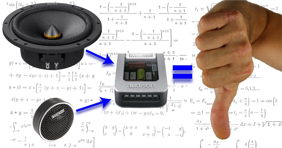
I often see people on Facebook Marketplace, eBay, Craigslist or Kijiji (in Canada) selling the passive crossover networks that came with their car audio component speaker sets. In most cases, these people have likely opted for an active system installation that uses a DSP and four dedicated amplifier channels to power their speaker system. An issue that many do-it-yourself car audio enthusiasts don’t seem to understand is that passive crossover networks are not universal. If the network was designed for a set of Audison Voce, Hertz Mille, Rockford Fosgate T3, Sony Mobile ES or ARC Audio Black-Series speakers, it won’t work properly with drivers from another series from the same brand or from other brands. In most cases, these networks differ for differently sized speakers in the same series.
What Do Passive Crossover Networks Do?
The purpose of a crossover network is to divide the sound energy produced by your amplifier into frequency ranges that specifically sized speakers can handle. In an active audio system, we use either a computer chip called a digital signal processor or an electronic filter network to limit what audio frequencies are sent to each channel. If we send only bass and midrange information to a pair of channels, then the woofers would be connected there. If we send only high-frequency information to a pair of channels, that’s where your tweeters would be connected.
As we’ve explained in other articles, passive crossover components like inductors and capacitors oppose the flow of alternating current signals, as we would find in audio system signals. Capacitors increase in impedance (opposition to current flow) at higher frequencies, and inductors increase their impedance at lower frequencies. It should also be clear that impedance isn’t the same as resistance. These components don’t get hot like resistors at normal operating levels.
The simplest passive filtering networks use a capacitor to block bass frequencies and an inductor to block high-frequency information. A capacitor would be used on the tweeter, and an inductor would be used on a woofer or midrange driver.
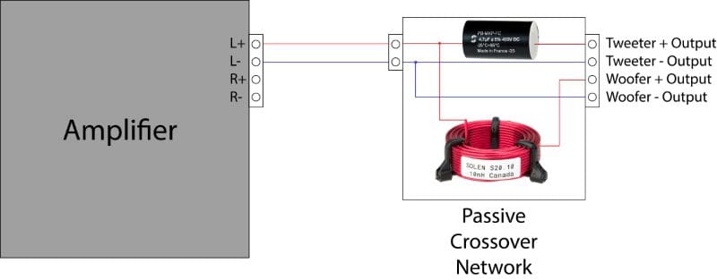
Passive Crossover Networks Are Complicated
The simplest passive filter network for a speaker set would have a capacitor on a tweeter. The vast majority of coaxial speakers include only a cap for the tweeter to prevent midrange frequencies from damaging it. Some entry-level component sets include simple inline filter networks for just the tweeter, hoping that the natural roll-off of the woofer or midrange driver will prevent any overlap. Better systems add a low-pass filter to the midrange to prevent overlap. If you’ve ever wondered what makes a particular component set better than another, the complexity and accuracy of the crossover are a big part of it.
The values of the capacitors and inductors used in a well-designed crossover are very specific. Indeed, there are generic crossover calculators, formulae and spreadsheets all around the internet. However, if ruler-flat frequency response through the crossover point is your goal (as it should be), then the process must start with impedance versus frequency measurements.
If you’re a longtime reader of our articles here at BestCarAudio.com, you know speakers are not resistors. Their impedance can change dramatically at different frequencies. A 6.5-inch woofer might have a nominal impedance of 4 ohms, but in reality, it may present anywhere from 3.5 to nearly 20 ohms of AC current opposition, depending on the frequency at which the measurement is taken.
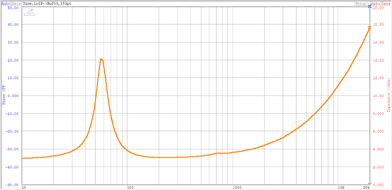
A quick look at the graph above shows the impedance of a 6.5-inch woofer with advanced inductance management features. This is far from typical in the car audio industry, even though the technology has been around for decades. Imagine that we want to calculate a simple low-pass crossover at 5 kHz for this driver. If we assumed the impedance was 4 ohms, the inductor we’d need to use would have a value of 0.13 millihenry. If we look at our chart, our woofer has an impedance of 8 ohms at 5 kHz. The inductor would need to be 0.25 millihenry to have a chance of providing the proper filtering. Right away, those online calculators that assume a nominal impedance of 4 ohms are wrong.
Sadly, the situation gets worse. The impedance of the driver continues to increase at higher frequencies. As such, the effect of the crossover would not provide the as-designed first-order attenuation we wanted. If we’d hoped for this to provide smooth output through the crossover region with a tweeter, we’d be very disappointed in the results.
The impedance of a tweeter also varies with frequency. Below is the impedance plot of a high-quality liquid crystal polymer-diaphragm tweeter. Around our 5 kHz crossover point, the impedance is very close to 4 ohms. What about down at the resonant frequency of the tweeter near 1.5 kHz? The impedance has risen to 6.7 ohms. What happens to the output of the tweeter at this frequency? Is it still protected from over-excursion damage by the crossover?
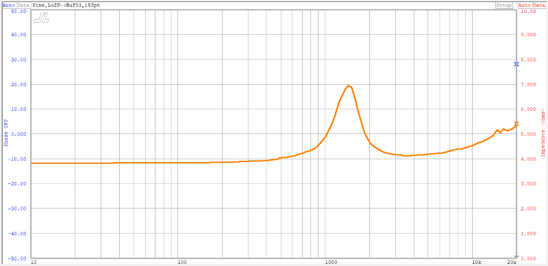
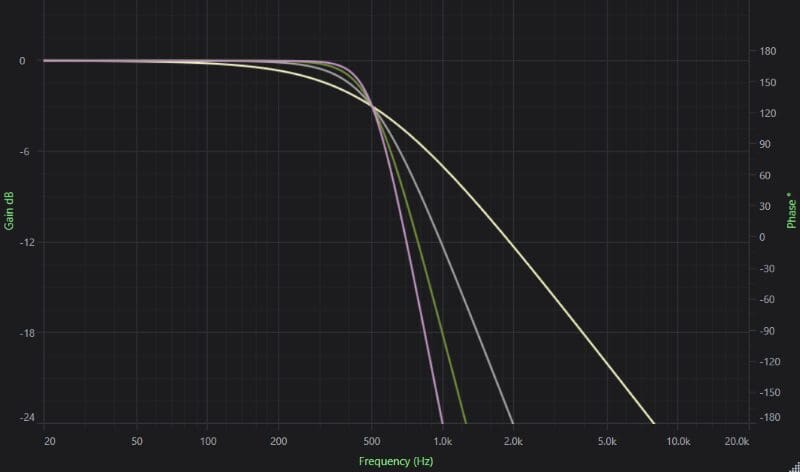
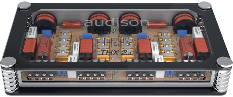
The above discussion of crossovers references simple single-component first-order (-6 dB/octave) filters. Most of the high-quality crossovers that come with top-end component speaker sets use second-order low-pass filters on the woofers and third-order high-pass filters on the tweeters. The specific value of every component in the network must be matched to the impedance response of the driver. If not, the resulting performance will be unpredictable and, most likely, undesirable.
Phase Is Another Problem with Crossover Design
Just when you thought things were complicated enough, we’re going to make it worse. Passive crossover components affect the phase response of the speaker system. We’ll keep this simple and say that a capacitor on a tweeter results in a phase shift of 45 degrees around the crossover point. An inductor on a woofer at the same frequency results in a -45-degree phase shift (assuming you managed to pick the correct values to make the crossover points the same) at the crossover point. We now have the speakers halfway out of phase with each other at the crossover frequency (45 plus 45 is 90). These phase issues change the way frequencies sum around the crossover point. The phase relationship also changes if one driver is farther away from the listening position than another. In short, things get even more complicated very quickly.
Overlap and Underlap
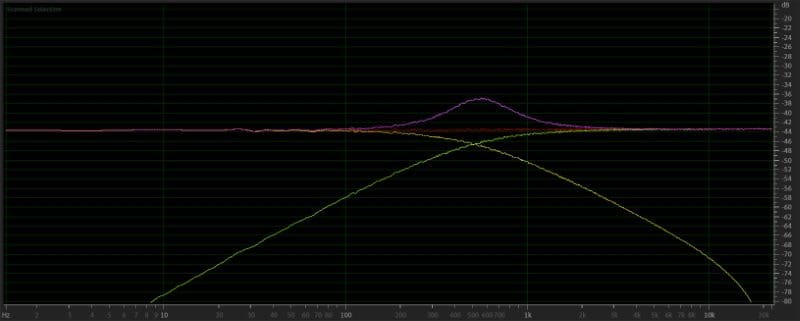
Here’s one more for you and a topic that we need to discuss at length with respect to electronic crossovers as well: In speaker systems, -3 and -3 don’t add up to 0. More specifically, if you were to design a passive crossover for a speaker and choose capacitor and inductor values so that both speakers were at an output level of -3 dB at the desired crossover point, their output would sum to +3 dB – not flat. When two speakers produce the same sound at the same levels, their output sums by +6 dB. For a first-order network, you need to underlap the crossover frequencies to make the system sum smoothly. Picking those frequencies would require real-world acoustic analysis of different component values for the drivers in mind.
Crossovers Vary by Application
It’s not just the impedance of the drivers that changes the values required in a passive crossover. Back in 2005, I reviewed a set of Boston Acoustics SX60 component speakers. To that point, all the speaker measurements I published had been taken with the drivers 1 meter away from the measurement microphone, and on-axis with the system. After sending the data from my measurements to Boston Acoustics, they asked whether it was possible to position the microphone in a different location. They had designed the passive crossover networks included in the kit to work best when the tweeter was turned 60 degrees to the side and the system response with measured at a distance of 1 meter from the tweeter, putting it 60 degrees off-axis to the woofer. In this configuration, the response was ruler-flat. In the usual all-facing-forward design, there was a dip of almost 10 dB on either side of the crossover point. Before you get to thinking that there was something fancy going on in the crossover, the network had a single inductor for the woofer to form a first-order filter and a cap and inductor for the tweeter as a second-order filter.

It’s logical to determine that based on the above, many companies customize their passive crossover designs differently. Years ago, passive networks were often optimized to have the tweeter mounted in close proximity to the woofer. Some companies learned that the systems were more likely to be installed with the woofer in the stock lower door location and the tweeter up in the sail panel or the dash. They changed their crossover designs to be optimized for this application. There was a drawback, however: When the speaker systems were on display at a store, the included crossovers didn’t work well. Many companies also offer “display only” networks to their retailers to optimize on-display performance.
If you’re starting to think that these things are complex and finicky, you’re 100% right.
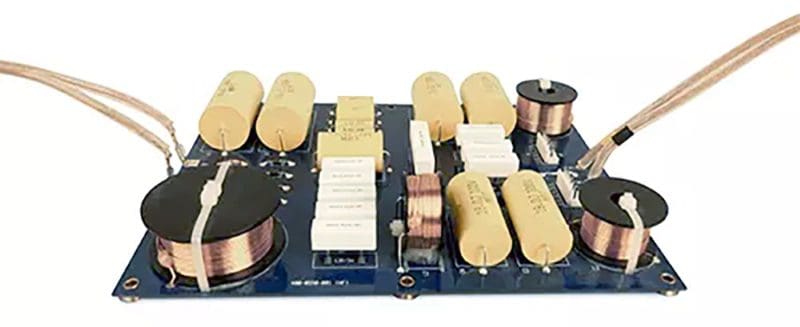
The image above is of the passive crossover network in the JBL 4367 home audio speaker. This network is high-pass filter for a single tweeter in one of the cabinets. The network includes five high-frequency and five ultra-high-frequency attenuation options. Complex networks like this are part of what makes high-quality home audio speakers expensive. A set of the 4367 speakers retails for about $16,500 ($22,000 Canadian), and they sound better than most systems at 10 times their price.
Testing Speakers with the Wrong Passive Crossovers
I have a set of Rockford Fosgate T3652-S component speakers in my test lab for a Test Drive Review. I’ve made my frequency response measurements using the supplied filter networks. Let’s see what happens to the frequency response when I use a network from different speaker systems. I’ll use a two-way passive network I developed when I worked for Clarion Canada Inc. This was the crossover for the Signature Series SSS501 5¼-inch component set.
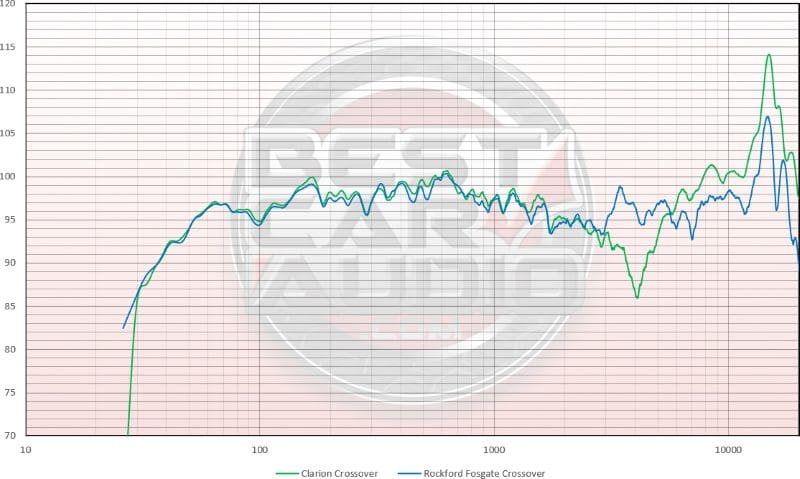
It’s easy to see that the Rockford Fosgate speakers don’t like the Clarion passive networks. There’s a 10 dB dip at 4 kHz, and the tweeter is 5 dB too loud at frequencies above 7 kHz. In short, this would sound terrible.
Can I Use Another Brand’s Passive Crossover with My Speakers?
Let’s get to the bottom line: Can you use a passive crossover network designed for a different set of speakers with the drivers you have? The answer is likely no. You might find a solution that works, but the odds of it delivering smooth frequency response is highly unlikely. You’d have to try dozens of networks, though.
Can you replace a driver in an existing system and expect the same flat frequency response? This is also very unlikely. You’re much better off adding another amplifier and using an electronic crossover or DSP to handle frequency division. A local specialty mobile enhancement retailer can help you choose an amplifier and frequency-filtering solution to ensure that your audio system sounds great.
