Somewhere around ninth grade, most high school students in North America learn about Ohm’s law in science class. Despite repeated efforts and claims to debunk the laws of physics, Ohm’s law remains a constant that car audio enthusiasts and professionals deal with every day. On a related subject, I see questions about speaker and amplifier wire sizing all the time. To help people get an honest answer to their questions about wire size, let’s step away from our usual educational path for a hands-on method of checking your existing audio system wiring to determine whether it needs to be upgraded.
BestCarAudio.com Mission Statement
Before we dive into math and science, I want to explain why you don’t see “how to” articles on BestCarAudio.com. Our mission is to educate consumers about the mobile enhancement solutions available from reputable specialty brick-and-mortar retailers. Nothing we do or explain is intended to educate our readers about how to install, fabricate, configure or calibrate their audio systems. We believe that those tasks are best left to professionals. The information we provide our readers explains how things work so they can cut through the myriad marketing stories to purchase solutions that sound great, offer excellent value and work reliably.
This article is a slight departure from that philosophy, because we think it’s a topic that very few people understand fully — and one that’s important to the industry.
Introducing Ohm’s Law
Ohm’s law quantifies the relationship between voltage, current flow and resistance in an electrical circuit. When 1 amp of current flows through a load with a resistance of 1 ohm, 1 volt will be dropped (present) across that load. If we increase the current to 2 amps, we get 2 volts across a 1-ohm load. We get 5 amps of current flow if we connect a 1-ohm load in parallel with a 5-volt supply. We also get 5 amps with a 1-volt supply and a 0.2-ohm load resistance.
The chart below shows how to rearrange amperage, voltage or resistance values to calculate a missing value.
You might recognize a pattern if you look at the triangle above and the three math equations below. Current is calculated by dividing voltage by resistance. Resistance is calculated by dividing voltage by current. Voltage is calculated by multiplying current by resistance. The arrangement of the letters in the triangle represents these equations and makes it easy to remember the formulae.
Car Audio Amplifier Wire Size
For this article, we’ll focus on measuring the suitability of wiring for a car audio amplifier installation. Wire size matters if you want your system to play as loudly as possible and if you want your amplifier to operate as efficiently as possible. Wire size matters if you want to reduce the load on the alternator in your car or truck. And wire size matters if you want to avoid starting a fire.
Car audio amplifiers are limited in terms of the voltage available from a vehicle’s electrical system. Most cars and trucks operate from 13.2 to 13.4 volts during daily driving. If you call on your amplifier to produce 100 watts of power, and it’s 80% efficient, it needs to consume 125 watts. The 125-watt value is determined by dividing 100 by 0.8. If the vehicle can produce 13.2 volts, the amp must draw just under 9.5 amps of current. The 9.5-amp value is determined by dividing 125 watts by 13.2 volts.
A current draw of 9.5 amps isn’t a big deal – that’s similar to a pair of incandescent headlight bulbs. What happens when you want an amplifier to produce 1,000 watts? If we could provide 13.2 volts at the amplifier’s power connections, it would consume 95 amps of current. Keep in mind that 95 amps is more current than the alternator in many compact vehicles can produce.
All Conductors Have Resistance
All conductors have some amount of resistance. A piece of 18 AWG braided wire should have a nominal resistance of 0.02833 ohm per meter or 0.00863 ohm per foot. With a piece of 4 AWG wire, it should be 0.00088 ohm per meter or 0.000268 ohm per foot. Even the traces on a circuit board or solder connections have resistance.
When current flows through something with resistance, a voltage is produced across that resistance. If you have a piece of 18 AWG wire and 10 amps of current is flowing through 1 meter of wire, you should measure 0.2833 volt across the wire – 10 amps times 0.02833 ohm is 0.2833 volts. That same 10 amps of current flowing through 1 meter of 4 AWG wire would produce 0.0088 volt.
Suppose we have a power supply, or more specifically, a battery and an alternator in our discussion of automotive applications. In that case, we want as much voltage as possible to reach the amplifier. If the wiring is undersized, the supply voltage will be wasted across that wire and not get to the amp. From an electrical perspective, the wire itself becomes a load.

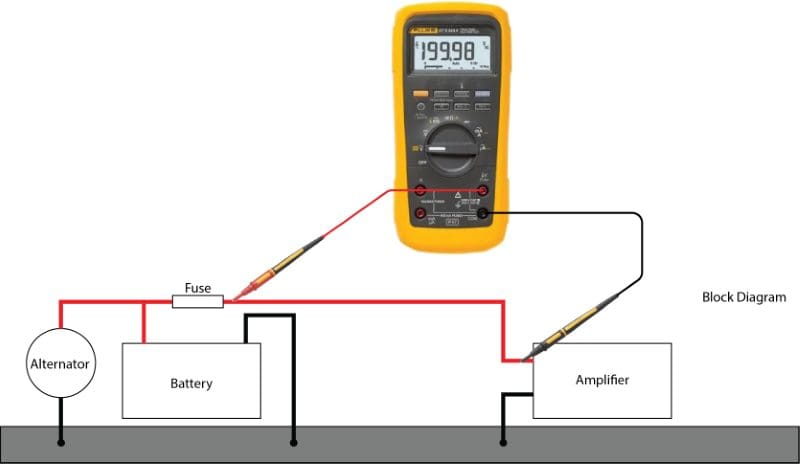
If we look at the block diagram above, we can see that the amplifier is our load, and it’s fed by power from the battery and alternator. For this example, let’s say we have an amplifier that wants to draw 100 amps of current. If the alternator and battery can produce 100 amps of current at 13.2 volts, how much of that voltage will reach the amplifier?
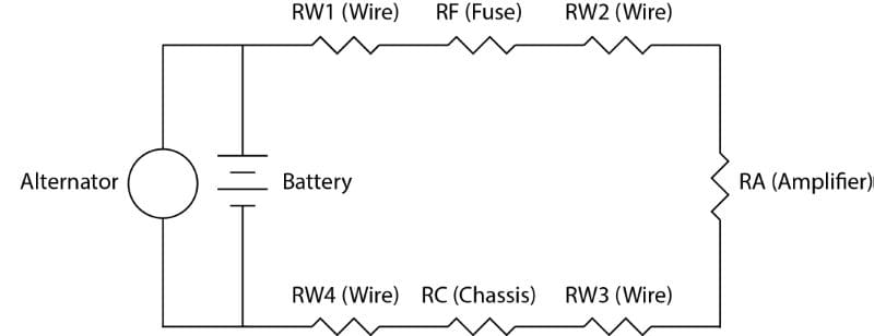
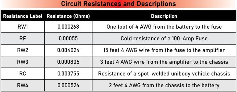
I’ve redrawn the system diagram as a schematic to help explain the importance of power wire resistance. This diagram doesn’t include the resistance in the wires from the alternator to the chassis and battery, but it gives you a good idea of what’s going on.
If we add up all these resistance values, we get a total resistance of 0.009938 ohm. That doesn’t sound like much, does it? When 100 amps of current flows from the alternator and battery through the wire, the amplifier and back to the source, this resistance results in 0.99384 volt being dropped across the wire. Our amplifier will only “see” about 12.2 volts. The amp won’t produce as much power and will clip earlier than if it were provided with 13.2 volts. If the amplifier is reasonably efficient, it might produce 1,000 watts of power with 100 amps of current and 13.2 volts. If the amp is only “seeing” 12.2 volts, it would theoretically need 108.2 amps of current. The increase in current would increase the voltage drop to 1.08 volts. In the real world, the amp would draw just under 110 amps of current, but the signal would be full of distortion and sound terrible, since very few amplifiers have fully regulated power supplies.
How to Determine Whether Your Wiring is Large Enough
The ANSI/CTA-2005 Mobile Electronics Cabling standard allows for a maximum voltage drop of 0.25 volt along any length of cable. Since we’ve included the fuse, chassis resistance and return path, our 0.99-volt calculated voltage drop value is high. Let’s calculate what voltage drops across the 15 feet of 4 AWG power wire: 100 amps multiplied by 0.0040236 ohm is 0.40236 volt. This is also a little high. Ideally, you need 15 feet of 2 AWG wire to feed an amplifier capable of consuming 100 amps of current. The voltage drop would be 0.25146 volt along a 15-foot length of 2 AWG wire when 100 amps of current pass through it.
Since most wiring sold for car audio systems is undersized relative to the full AWG specification or contains tin and aluminum, it’s nearly impossible to know its resistance per meter or foot. Ultimately, all we want to know is how much voltage is being wasted, which is very easy to measure. I’ll show you how.
You’ll need a digital voltmeter. It doesn’t have to be a fancy Fluke or B&K Precision model; you can use a $7 Harbor Freight meter with reasonable success. Higher-quality meters will read faster and more accurately, so you might not want the least expensive unit you can find.
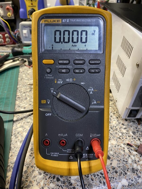
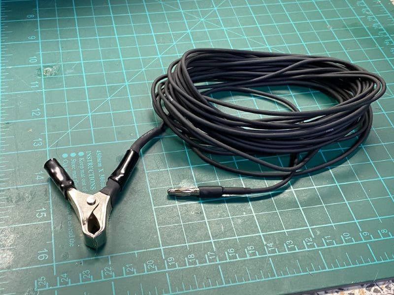
As shown in the above image, set the meter to measure DC voltage and connect the test leads to the Common and Voltage input terminals. You will also need a length of wire – something around 18 AWG in size and long enough to reach the back of your vehicle, so maybe 15 to 20 feet. If you’re doing this test frequently, you may want to get a 4-mm banana plug and a large alligator clip and solder them to the long piece of wire.
Test the Test Equipment
If there is one important lesson I can share before we start, that is to test the test equipment. Before we start measuring how much voltage is dropped across the wiring in our vehicle, we need to know that the meter and cables we’re using are functioning properly.
Take the ends of the test leads from your meter and measure the voltage at the battery terminals and amplifier power terminals with the audio system off. You should see nearly identical readings at both locations. The voltage is likely to be around 12.5 volts with the vehicle off or between 13 and 14 with the engine running. If the voltage doesn’t increase with the engine running, there’s likely something wrong with your alternator.
Here are the test steps:
Step 1 – Start the vehicle.
Step 2 – Have a friend turn on your audio system and prepare a low-frequency test tone. Do not use music. We will need a steady-state reading.
Step 3 – Connect the extended test lead from the meter to the output connection or terminal of the fuse or circuit breaker near the battery.
Step 4 – Touch the other test lead to the amplifier’s positive terminal.
Step 5 – Have the friend turn up the volume on the radio to whatever your installer said was maximum. Note the volume level.
Step 6 – Record the voltage displayed on the meter.
Step 7 – Reduce the volume on the radio.
Repeat the same steps on the amplifier’s ground terminal and the battery’s negative terminal using the same volume level on the source unit. Record that value.
Measurement Notes
If you measure a negative voltage, don’t fret. That means you have the leads reversed. The absolute value of the measurement is all that matters. In short, if you measure -0.55 volt, that’s the same information as if you measured 0.55 volt. You don’t have to repeat the test.
Depending on the meter you’re using, you may need to adjust the voltage range scaling. Some meters have a separate volts and millivolts scale. Adjust the meter so you can see as much detail as possible.
If you see a high voltage (12+ volts), you aren’t measuring across the length of just a piece of wire. One of the test leads is in the wrong spot. Refer to the diagram above.
Choose your test tone so that your subwoofer amplifier makes as much power as possible. This is usually at a frequency between 40 and 50 hertz and well away from the tuning frequency of a vented subwoofer enclosure. If there is a DSP in the vehicle, you’ll have to ask your installer what frequency on the subwoofer channel was boosted the most or cut the least. Feel free to try a few different frequencies to ensure that the test works. More voltage drop means the amplifier is drawing more current and making more power.
You may also notice that the voltage you read across the wire increases the longer you perform the test. This is because the wire is heating up. When a conductor gets hotter, its resistance increases. The longer you play your audio system, the hotter the wire will get, and as such, the voltage wasted in the wire will increase. This results in a decrease in how much power your amplifier can produce.
Don’t do this test for much more than a few seconds. Your subwoofers, alternator and battery won’t enjoy it.
Understanding the Test Results
If all the power wiring is sized appropriately, neither voltage measurement should exceed 0.25 volt. With that said, if you aren’t competing to see who has the loudest car audio system, a drop of 0.5 volt is acceptable. The cost per ton of copper doubled between March 1, 2020, and May 1, 2021. Good quality power and ground wire are costly right now, so it’s OK to be a little under-sized if you aren’t looking for every watt of power out of an amplifier.
Secondly, we typically listen to music that has lots of dynamic range. Under most day-to-day listening conditions, it’s not likely that you’ll be commanding full power out of your amp for long periods . Even with the music hitting an amp’s maximum output capabilities, the average current consumption is likely to be less than 25% of the maximum current. It all depends on the music you listen to and where the volume on the radio is set.
If you are a bass-head, then the 0.25-volt drop is the most you’d want to see. For daily driver systems, a 0.5-volt drop is acceptable. Keep in mind, that less voltage across a wire is ALWAYS better.
Car Audio System Power Wire Upgrades
Let’s look at what happens if we wire the system in our diagram with different sizes of power wire. If you were to wire the above system with 0 AWG full-copper wiring, the voltage drop would be 0.094 volt. If you did the same installation with a high-quality 8 AWG cable, the voltage drop would be 2.41 volts.
I’ve tested wire from many manufacturers and suppliers over my career. I’ve seen copper-clad aluminum wire that was so undersized and with so much aluminum content it had 2.7 times as much resistance as name-brand CCA wire, which has more resistance than tinned copper, which has more resistance than an all-copper conductor. Unless you’ve tested the resistance of the wire, never assume anything about its current carrying capacity. As a side note, you can’t accurately gauge wire size by weight. A rubber jacket would be heavier than a PVC jacket. I recently saw someone purporting that their wire weight chart was the be-all and end-all of wire shopping tools.
What To Do if You Measure Too Much Voltage Drop
The voltage drop test that’s outlined above can be used for any electrical system where you’re concerned about a bad connection or undersized conductor. It works on wire from a remote-mounted battery kit or wiring to a high-power ignition module or cooling fan. If you think a fuse or circuit breaker is bad, measure the voltage across it.
If you measure too much voltage across a conductor, the easiest solution is to have your installer upgrade the wire to something more suitable for the system’s current consumption needs. You can also add a second power wire run, which should cut the voltage drop in half – if you use the same conductors.
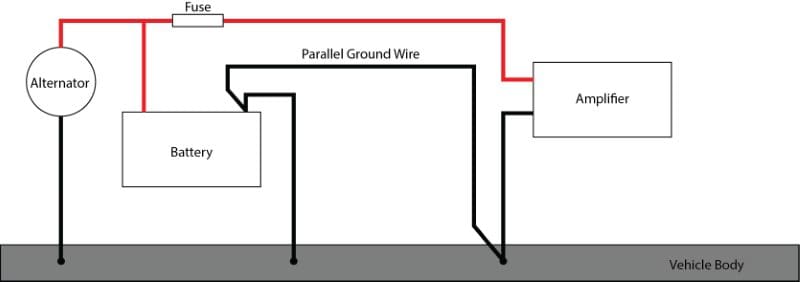
If the voltage drop problem is on the ground side, the vehicle chassis is likely the issue. I recommend having your installer run a parallel ground from the rear ground point to the negative battery terminal. This extra ground path is especially critical on new vehicles that use adhesives instead of spot welds to attach body panels together.
Keep Your Car Audio Amplifier Happy
Hopefully, the information presented here makes testing the power wiring in your car audio system easy. If you’ve purchased an amp kit online, you’ll want to do this test to see how bad it is. If you need upgraded wiring in your vehicle, drop by a local speciality mobile enhancement retailer and present your findings from this test. They should be happy to help, and your amplifier will appreciate the extra voltage.
