If you were into car audio in the ’80s or ’90s, you undoubtedly heard about people spending countless hours hunting down engine noise or alternator whine issues with amplified systems. Thankfully, modern high-quality car audio amplifiers include circuitry on the RCA input jacks that nearly eliminates the chance of ground loops and prevents the audio system from producing unwanted noises. These differential input circuits are a “must have” feature on modern amplifiers. In this article, we’ll explain how to test an amplifier to ensure that it uses this type of RCA input circuitry.
What Is a Differential Input Circuit?
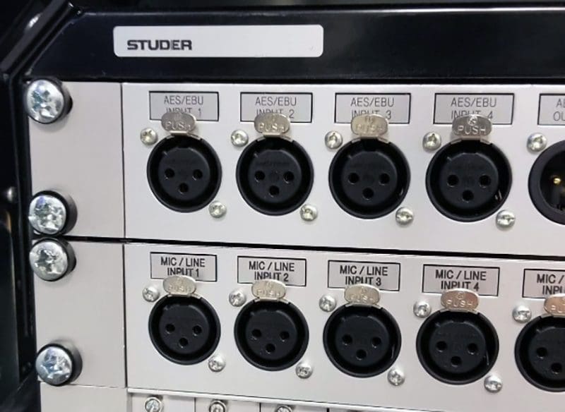
Differential input circuits are also known as balanced inputs. They’re similar to what pro-sound and recording studio audio equipment use with XLR connectors, except that there are only two connections instead of three. In a fully balanced signal, as found on XLR connectors, the audio waveform is present on Pin 2, and an inverted or reverse-polarity copy of that waveform is on Pin 3. A ground wire is connected to Pin 1. The circuitry inside the amplifier, processor or mixer compares the waveform on Pin 2 to that of Pin 3. Anything common to both is rejected, and the difference between the two is sent through to the device for amplification, processing or mixing.
Let’s take a graphical look at how pro audio balanced connections work.
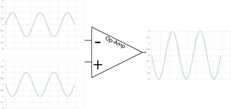
The top left waveform in the above image is our original audio signal. It would represent what would be seen on Pin 2 of an XLR connector. The bottom left waveform is the same signal but has been inverted in terms of polarity. This is the signal we’d see on Pin 3. When we subtract the signal on Pin 3 from Pin 2, we get the output waveform on the right of the image. The amplitude is twice as high because subtracting a negative value is like adding a positive. For example, 1 minus -1 is 2.
Now, what happens if both conductors pick up noise along the way from a microphone, guitar or synthesizer to the mixing console? We get the result shown below.
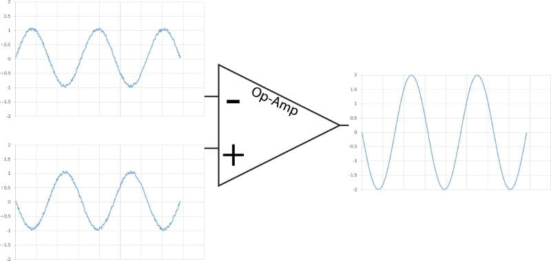
The image above has the same configuration, but now we show noise added to the positive and negative waveforms. The noise is random but is equal in polarity and amplitude on both Pin 2 and Pin 3. Because the polarity of the noise is the same, subtracting the noise on Pin 3 from the noise on Pin 2 results in just the audio signal passing through.
Car Audio Interconnects and Noise Cancellation
In car audio applications, we use RCA interconnects with only two connections: a signal wire on the center pin and a ground on the outer shield. Inside the amplifier, the center pin on the RCA cable carries the same signal we’d find on Pin 2 of the balanced connector. The shield on the RCA is treated like Pin 3. Any signal (noise) common to both connections is rejected, and anything different is passed through to the processor or amplifier.
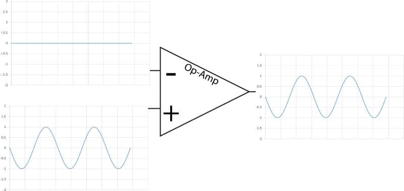
The above image shows how the differential input circuit works when there isn’t any noise on the shield or the center pin of the RCA interconnect cable. The result is a clean signal sent to the processor or amplifier.
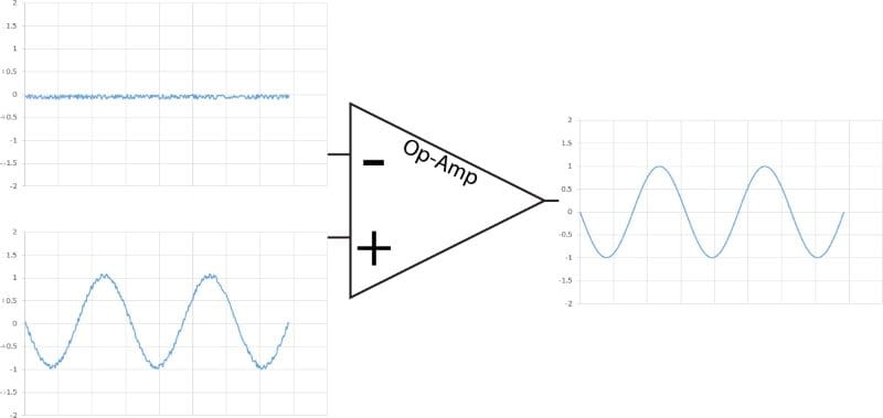
As long as the noise is equal in polarity on both the center pin and the RCA jack shield, the differential input circuit will subtract the noise on the shield from the noise on the center conductor and cancel it out.
Differential Input Circuitry
The image below is the schematic (minus the component values) for a differential input circuit from one channel of a premium car audio amplifier. The two circles on the left represent the RCA jack. The op-amp is the triangle with the plus and minus signs in the middle. The sawtooth-shaped components are resistors, and the components with the two parallel lines are capacitors. The triangle at the bottom represents the chassis ground.
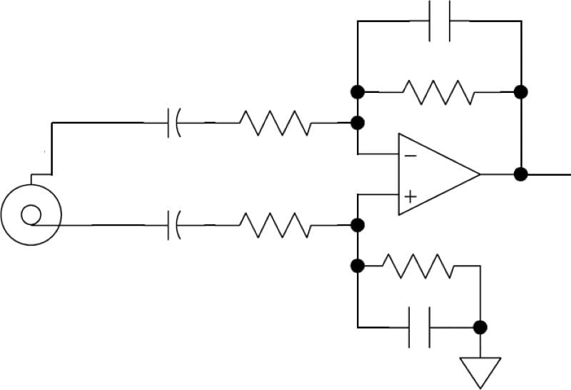
The op-amp (short for operational amplifier) does the work in this circuit. It subtracts the signal on the negative input from the positive one. So if we look at the connections, it’s subtracting the signal on the RCA shield from the signal on the RCA center pin.
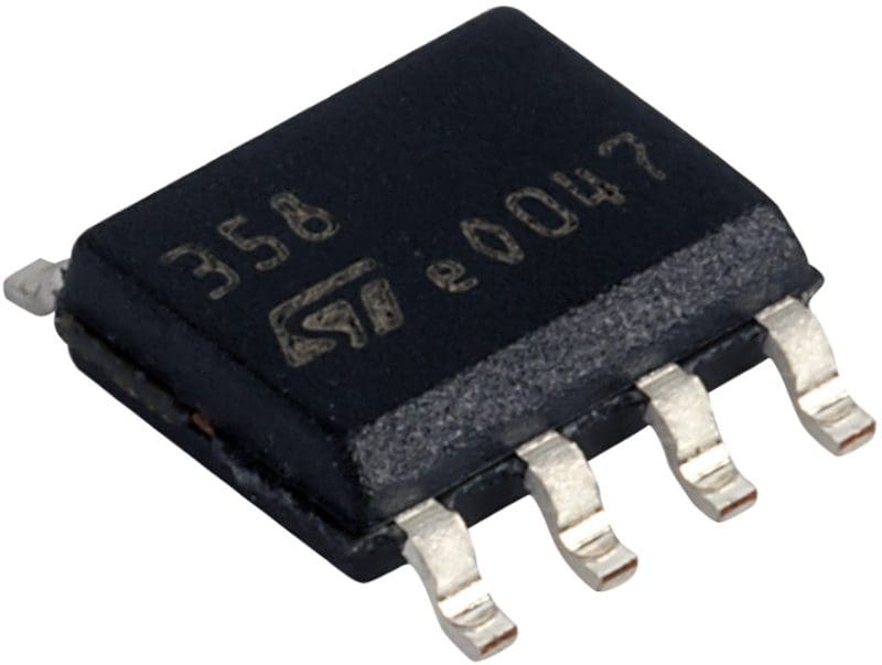
The image above shows a dual op-amp in a small-outline integrated circuit (SOIC) case. This is a typical example of what would be used to handle the balanced input processing on a pair of stereo input jacks. The “dual” in the name means that it has two separate circuits in the single chassis. The SOIC case is designed for surface-mount installation. If the amp you’re looking at uses through-hole devices, it’s likely an archaic design.
Why Don’t Balanced Inputs Have Ground Loops?
A ground loop is one of the most common sources of unwanted noise in an audio system. A ground loop happens when the ground potential of one component (radio, processor or amplifier) is different from another. Without differential circuitry, current will flow through the shield of the RCA interconnect cable to equalize the ground voltages. However, in an amplifier or processor with balanced inputs, the shield of the RCA cable isn’t connected directly to the ground. Instead, the shield is only connected to the op-amp’s negative terminal, which will compare the waveforms of two connections. As such, current can’t flow through the interconnect shield and induce noise into the system.
What about noise caused by an interconnect running beside a source of electrical interference? As long as the signal picked up is common to both wires, the differential circuitry subtracts it from the audio signal. The subtraction isn’t absolute, though. In most cases, good-quality audio equipment can reduce the amplitude of interference on the interconnect by around 60 dB. This attenuation is usually enough to make it very difficult to hear when music is playing.
All Car Audio Equipment Should Have Balanced Inputs
If you’re shopping for audio components for your car stereo and want the benefit of balanced input circuitry, all your amplifiers need to share the same input type. If one amp is balanced and the other is single-ended, you can still get unwanted noise in the system.
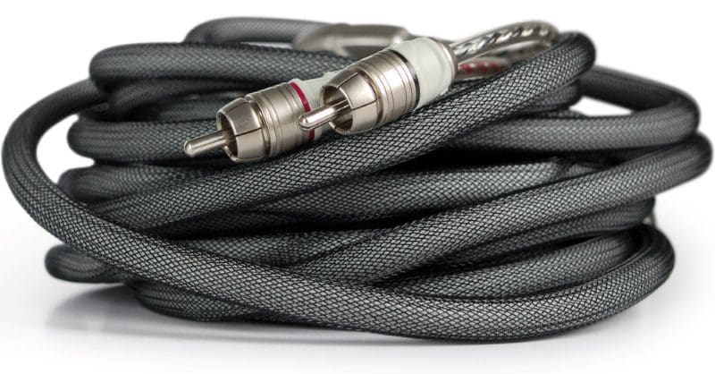
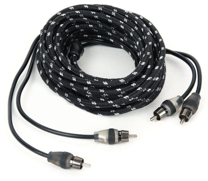
Secondly, your system must be wired with twisted-pair interconnects for the balanced input circuitry to function. You can’t use coaxial cables. A coaxial cable shields the center conductor from electromagnetic and radio-frequency interference. If a coaxial cable is connected to an amp or processor with differential inputs, noises are not common to both conductors and can result in unwanted sounds being reproduced by the downstream device.
Let’s look at what happens if you use a coaxial interconnect cable with an amplifier with differential inputs.
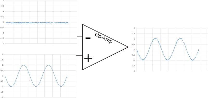
The image above shows that some noise has been picked up on the interconnect shield. Because the center conductor has another layer of insulation around it, it might not pick up the noise. When this combination is passed through the op-amp, the result is a noisy signal.
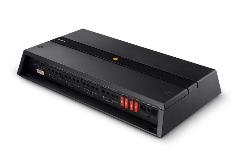
How To Test an Amplifier To Ensure that It Has Differential Inputs
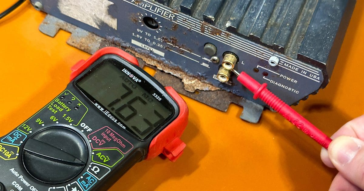
Testing an amplifier to ensure that it has differential inputs is very easy. We’ll describe two methods. For the first, you’ll need one tool: a digital multimeter. With nothing connected to any of the input terminals and the multimeter set to the lowest resistance range, measure the resistance between the shield connection on the RCA input jack and the common terminal of the speaker outputs. You should see a relatively high resistance or a completely open circuit. If you see a low impedance like 1,000 ohms, the amp likely doesn’t have differential inputs.
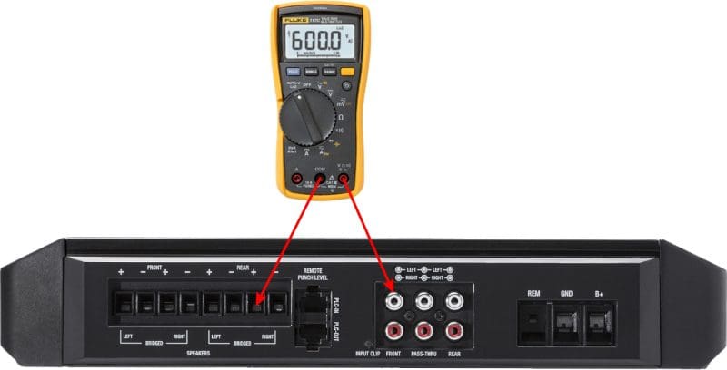
What is the common terminal of the speaker outputs? Assuming the amplifier you’re testing is a two-channel bridgeable design, the common terminals are the speaker connects that aren’t used when you bridge the amp.

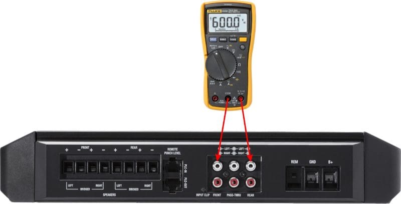
The second method of checking for differential inputs is to measure the resistance between the shield on two different inputs. Once again, you should see a high impedance or a completely open circuit.
Since we’re talking about it, we’ll throw in two more options.
If the amplifier accepts speaker-level signals directly from a radio on the RCA terminals, the chances are very good that it has differential inputs.
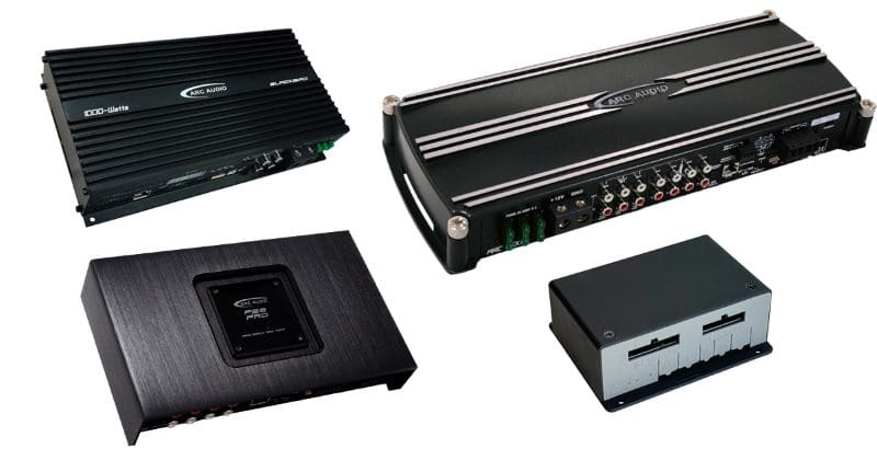
Finally, if you aren’t sure if the amp or processor you are considering has differential inputs, call the manufacturer. Ask them if it does. Ask for the common mode rejection ratio (CMRR) measurement if you question their answer. If they can’t answer the question or provide details, the device likely doesn’t have differential inputs and isn’t a good choice for your car audio system upgrade.
That’s it. There’s nothing complicated about it.
Choose Car Audio Equipment with Balanced Inputs for Maximum Performance
Can an audio system component with unbalanced inputs work well? Most definitely. Some of the best amplifiers use single-ended inputs. With that said, the chances of having to rewire components in the system if there is noise are much higher. We’ve heard of people spending days chasing down unwanted noises in these systems. Every modern car audio component designed by an engineer who understands how differential circuitry works would and should use this input type. You’ll find lots of low-quality internet brands that don’t. Browse social media for a few minutes and you’ll find many examples of the owners of these products asking for help to eliminate noise. From our perspective, if you stick with name-brand products that use differential inputs, you’ll save your installer from this sort of headache and save yourself from all kinds of unwanted noise.
Drop by a specialty mobile enhancement retailer near you and ask about the features of the amplifiers they offer. One of the easiest ways to keep noise out of your car audio system is to choose an amp with differential inputs, pair it with a radio with a strong pre-amp output and ensure that the gain controls are set correctly.
EDIT: Our friends at ARC Audio saw this article and have offered some additional information on testing differential input circuitry. Check out this article!
