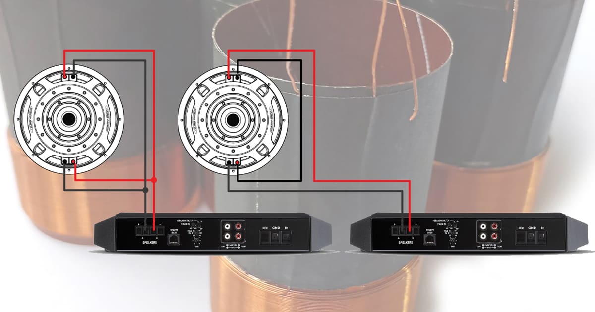
Any time your installer wants to wire two subwoofers to the same channel of an amplifier, they can wire them in series or parallel. The same goes for a dual voice coil design subwoofer. The only benefit of a DVC subwoofer over a single is that there are three wiring options. We examined whether the wiring options for dual voice coil subwoofers differed a while back. Thinking about this article, we realized we had skipped over the basics of what happens when a single DVC subwoofer has its coils wired in series or parallel. The wiring options are simple, and the results are fairly predictable.
Subwoofer Parameters and Voice Coil Wiring
We can describe the physical characteristics of a subwoofer (or speaker) using a set of Thiele/Small parameters. This electromechanical information allows software or a spreadsheet to calculate how a moving coil speaker will behave when used in an enclosure that serves as a high-pass filter. Functionally, characteristics like the free-air resonant frequency of the driver, the moving mass and the suspension compliance are independent of how an installer wires the voice coils. For this article, all that will matter is the change in impedance.
Impedance is the opposition to the flow of alternating current. It’s similar to resistance, but in the case of a subwoofer, it varies with frequency. Impedance can be affected by resonance, inductance and capacitance, though the latter isn’t a significant issue for speakers.
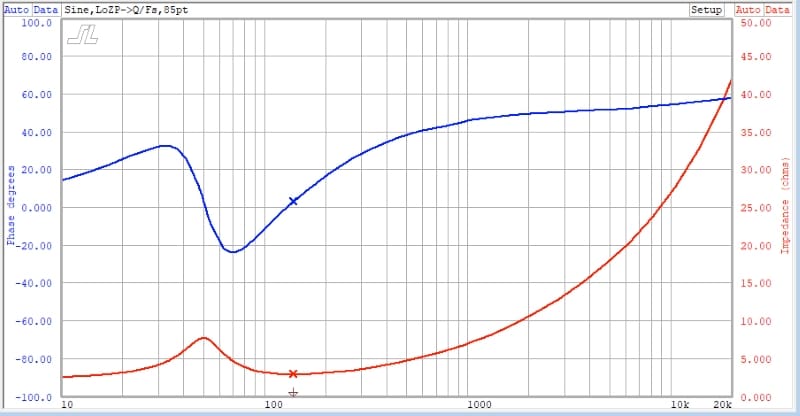
Inductance is an opposition to alternating current flow caused by magnetic fields. Many of us who have been in the car audio industry for a while will recall using passive crossover components like inductors and capacitors as filters. Modern car audio systems typically use a digital signal processor and multiple amplifier channels to perform the same task.
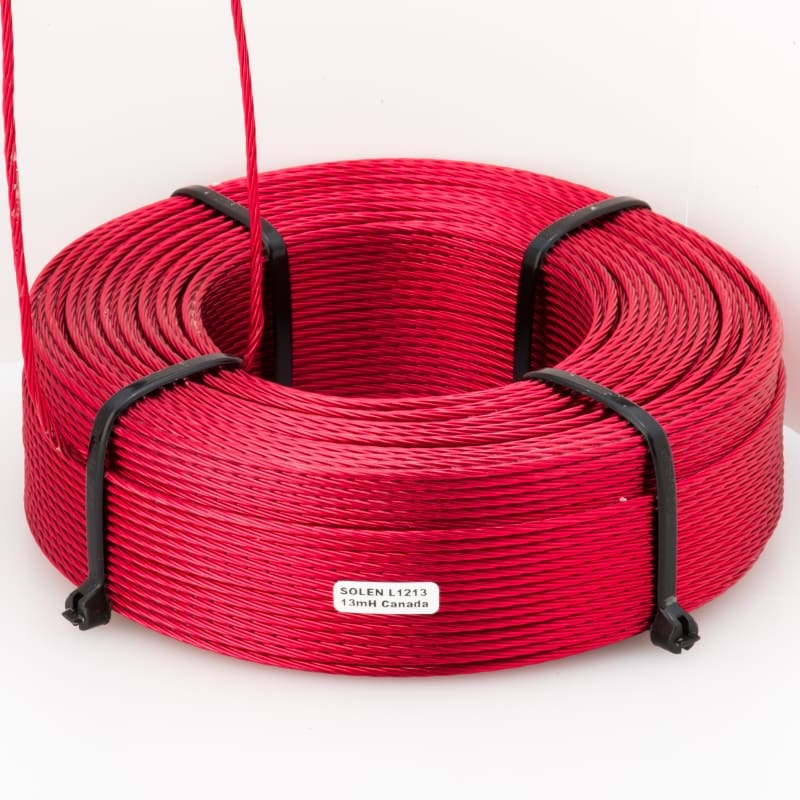
An inductor is simply a length of wire wound in a loop, just as you’d wind up an extension cord or garden hose after you use it. The inductor’s loop is typically much smaller and will fit in your hand. As current passes through the inductor, it creates a magnetic field. When the direction of the current changes (as it does with AC), the magnetic field opposes that change. An inductor provides more opposition to current flow at higher frequencies as the direction of flow changes faster.
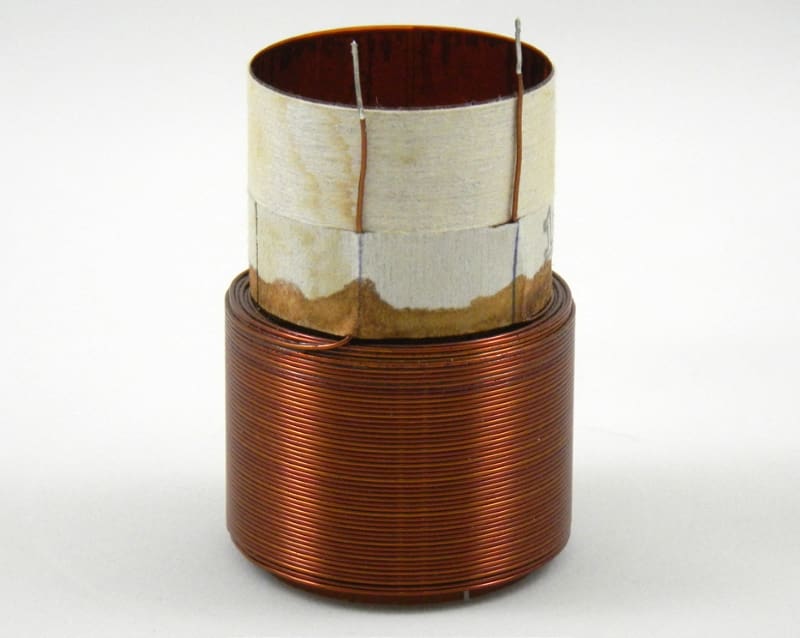
A voice coil in a subwoofer is the same as an inductor. We’ve seen many subwoofers with above-average power ratings with four- and six-layer voice coils. While these larger voice coils handle more power, their added size increases inductance because of the additional layers. This increased inductance means less midrange or midbass output. The added mass of the extra windings also affects midbass performance, as it’s harder to accelerate heavier objects.
Series and Parallel Wiring Versus Output
Our testing will highlight a few simple facts. First, car audio amplifiers increase voltage. How much power they make depends on the impedance of the speakers connected to them and their current delivery limits. If an amplifier produces 2 volts, and we have a 4-ohm voice coil, then 0.5 amp of current flows through the voice coil. The result is 1 watt of power sent to the subwoofer. If we have the same voltage and an 8-ohm voice coil, only 0.25 amp of current flows, and the sub gets 0.5 watt of power. If we have a 2-ohm subwoofer, the current doubles from our 4-ohm calculations, and we have 2 amps of current and 2 watts of power.
Whenever you double or half the power sent to a speaker, the acoustic output goes up or down by 3 dB SPL.
So, 2 volts into a 4-ohm subwoofer might produce 86 dB SPL of output measured at a distance of 1 meter. If every other parameter stayed the same, but the subwoofer in question had an impedance of 8 ohms, we’d only measure 83 dB SPL of output. A 1-ohm subwoofer would produce 89 dB SPL with 2 volts. Keep in mind, in the real world, other parameters change as the impedance of the voice coil changes. The differences might not be significant, but they are measurable.
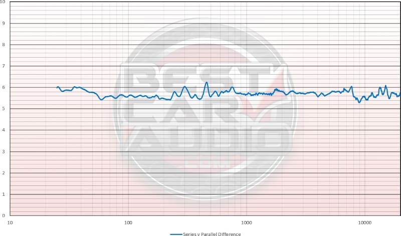
Changing the wiring of a dual voice coil subwoofer from series to parallel should produce 6 dB more output, assuming our amplifier produces the same voltage into both impedances.
Drawbacks of Low Impedance Loads on Amplifiers
As mentioned at the beginning of this article, selecting the impedance to run can be a bit complicated. In the hundreds of amplifiers that have crossed the BestCarAudio.com test bench, every single one proved less efficient at lower impedance loads. So while you might get a bit more power, you also consume a disproportionately larger amount of current and cause the chassis to heat up faster.
Most amplifiers we’ve tested also add more distortion to the audio signal at lower impedances. For some, this was significant. So, lower impedances often equate to a decrease in sound quality.
The product specialist helping you with your audio system design has to choose woofers that work with your amplifier’s specifications to produce the desired power output. There’s no sense in buying a 1,500-watt amplifier to run it with an 8-ohm load and have it only produce 400 watts, right? You could buy a 400-watt amp to get the job done. The big amp might have some sonic benefits, but not enough to make the added expense worthwhile for most people.
Measuring Output with Different Subwoofer Voice Coil Wiring Configurations
We have several subwoofers in the BestCarAudio.com lab for testing for our Understanding Subwoofer Quality series. The first measurement we will make is the frequency response of a 10-inch dual voice coil subwoofer with the coils wired in parallel. You can see that below.
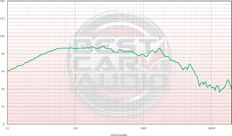
On its own, there’s nothing remarkable about this measurement, other than the subwoofer exhibits quite good midbass performance. With the voice coils wired in parallel, we measure the lowest possible impedance for the driver.
For the second measurement, let’s wire the voice coils in series. We won’t change the signal generator or amplifier settings for this test.
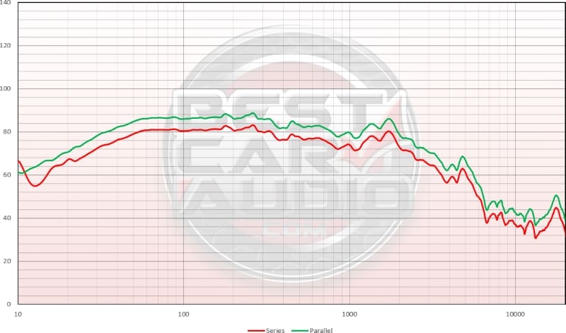
As expected, we see a difference of just under 6 dB SPL. Why don’t we see precisely 6 dB? Well, the output impedance of the amplifier acts like a voltage divider. At lower load impedances, the amplifier wastes more of the amplifier’s output power as heat.
The graph below shows the difference between the two measurements. Ignore the variances below 30 hertz; that’s just background noise in the test lab.
When we combine the options of wiring voice coils in series or parallel and add those same options for multiple drivers, we have a variety of options to create a net load impedance for our amplifier. If you want to understand more about wiring subwoofers in series and parallel, check out our article called Subwoofers and Amplifiers – Let’s Talk About Ohms and Loads. You may also want to read up on why some amplifiers don’t double their output power as the load impedance is halved in this article. If you still want to ask your installer to wire an amplifier up so it’s driving the lowest impedance it can, read this amplifier efficiency article.
As always, drop by a local specialty mobile enhancement retailer to learn about the best options for adding subwoofers to your car, truck, SUV, boat or motorcycle. They’ll be happy to take care of the installation and worry about picking suitable subwoofers and wiring combinations to ensure that the subwoofer amplifier you’ve chosen operates reliably and sounds fantastic.
