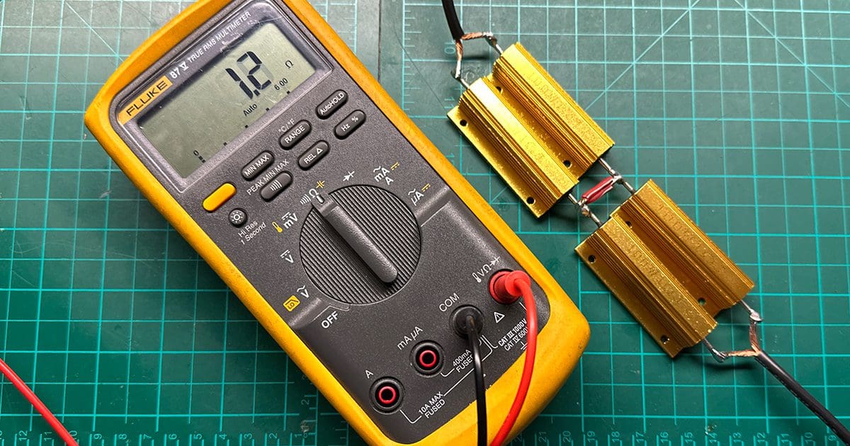
One phrase that is repeated time and time again during the installation troubleshooting process is that an amplifier ground is “good” because there’s only 1 ohm of resistance. If you’re a fan of the laws of physics, hearing this phrase should be met with an instant wince or cringe. Everything related to designing, installing and calibrating car audio systems has a foundation in physics, from understanding ohms, volts, amps and watts to the ones and zeros that store audio data and the resonances and reflections that alter what we hear from our speakers.
None of this is in any way complicated, and most of it harkens back to high school physics classes. If your attention was focused on music, video games or partying rather than academics, you might have missed out on a great opportunity to learn these important concepts. Fret not; BestCarAudio.com is here to break it down for you and explain why the 1-ohm amplifier ground statement is nonsense.
Ohm’s Law
There is a defined relationship between voltage, current flow and resistance in any conductor or circuit. This relationship isn’t flexible or debatable, and as such, Ohm’s law describes how much current will flow for a given voltage and resistance.
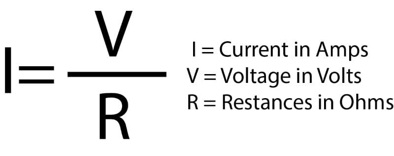
The law states that 1 amp of current will flow through a conductor or device (load) that has a resistance of 1 ohm when 1 volt is applied across the load. If we double the voltage, twice as much current flows. If we double the resistance, half as much current flows.
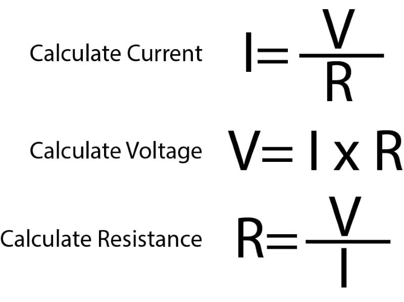
If we are supplied with two values (ohms, volts or amps), we can determine the third using simple mathematics. A circuit through which 5 amps flow and has 2 ohms of resistance must be fed by 10 volts. If we apply 15 volts to a circuit with a resistance of 3 ohms, 5 amps of current will flow. If 5 amps of current are flowing through a 5-ohm resistor, we know 25 volts were applied to the resistor.
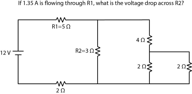
If you happened to take electronics in college, you may have been given schematics in the first semester with five to 10 resistance values. You would have been expected to calculate the voltage, current and resistance in each branch and the totals for the circuit. This is “Day 1” theory for anyone working on audio equipment or the electrical system in a vehicle.
Let’s Talk About Amplifier Current Requirements
Car audio amplifiers have a difficult task. They are often asked to produce hundreds, if not thousands, of watts of power to speakers and subwoofers, yet are only provided with 12 to 14 volts from the vehicle’s electrical system. As such, they draw a significant amount of current. A high-quality amplifier like the Rockford Fosgate M5-1000X1 I reviewed a few years ago produced 975 watts of power into a 1-ohm load when supplied with 13.75 volts and 98.5 amps of current.
Lower quality amplifiers are much less efficient. For example, I’ve tested a popular subwoofer amplifier from a European company that, while producing 935 watts of power, consumed 120 amps of current at 13.4 volts. That’s an efficiency of 58%, compared with 72% for the Rockford Fosgate. That extra 14% of the energy from your vehicle’s electrical system would be wasted as heat, which explains part of why that amp went into thermal protection in just three minutes.
Nevertheless, nobody will argue that car audio amplifiers can consume massive amounts of current. As such, the resistance of the wires used to power the amp must be very low. By way of an example, let’s say our installer ran a piece of four-AWG all-copper power wire from the negative terminal of the amplifier right to the chassis of the alternator. The ground wire is 15 feet long and is fully compliant with the ANSI/CTA-2015 standard for mobile electronics wiring. As such, the wire would have a total resistance of about 0.004023 ohm. If 100 amps of current is flowing through the wire, we’d see a voltage drop of 0.4023 volt across the wire. That’s not terrible, but also not great. Remember, we’ll see that or more dropped along the positive power wire and the fuse holder, so we are losing about a volt and maybe 10% of the amplifier’s capabilities because of cable losses. This is how Ohm’s law works.
Check Your Grounds?
When troubleshooting amplifier noise issues, one of the common suggestions is to “check your ground.” The number of times I’ve seen a reply of “I checked it with a multimeter; it’s about 1 ohm” is both astonishing and frustrating.
Let’s consider Ohm’s law again for a moment. If we have 1 amp of current flowing through 1 ohm of resistance, we know that there will be a potential of 1 volt across that resistance. Let’s bump things up in terms of current to 10 amps. With 10 amps of current flowing through 1 ohm of resistance, we’d measure 10 volts across the resistance. If the amplifier ground connection in a vehicle had 1 ohm of resistance, there might only be 2 to 4 volts at the amplifier terminals. I don’t know of any amplifiers that would stay on at a voltage that low.
Your Multimeter Isn’t Good at Testing Low Impedances
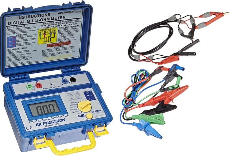
One of the first issues with the “1-ohm amplifier ground” is that most people are using the wrong tool to make the measurement. Even if you have an expensive Fluke, Snap-On, Keysight or B&K Precision True-RMS meter, it’s not good at measuring low-value resistances. Take your meter and put it in the lowest resistance measuring range, then touch the leads together. You’ll see a reading of something like 0.2 or 0.3 ohm if the meter is of reasonable quality, but you might see a few ohms on a low-cost solution. If you need to measure the value of a 100- or 1,000-ohm resistor, your multimeter is fine. For the small stuff, it’s not.
Now imagine testing our 15-foot length of four-AWG wire. You put the meter on each end of the wire and it will likely say the same thing – 0.2 or 0.3 ohm. If you hadn’t tested the meter with the leads shorted, you’d think that was accurate. Since we know the resistance is close to 0.004 ohm, do you expect to get an accurate reading from a multimeter? I hope not.
Let’s Test a 1-Ohm Amplifier Ground!
Explaining concepts and the laws of physics can be tough for people who are visual learners. As such, let’s see what happens when the amplifier ground connection has a resistance of about 1 ohm. I purchased four 1-ohm, 100-watt resistors, and I am going to wire them in a series/parallel configuration that will present 1 ohm of resistance with the ability to dissipate 400 watts of thermal energy.
Now, I’ll wire the resistor network in line with the ground wire on that M5-1000X1 amplifier that I mentioned earlier. I keep this amplifier on my test bench and use it for breaking in speakers and subwoofers before I review them. It’s been a tank and performs flawlessly, even when running for days at a time.
A few things to know about the amp. First of all, it draws around 1.3 amps of current when powered on but not amplifying an audio signal. If the resistance of my network is accurate, I should see a voltage drop of around 1.3 volts across the resistors. I measured 1.37 volts. So, the amp started off by getting only 12.26. volts when the power supply was providing 13.63 volts. This is the sort of voltage drop you’d want to see when an amplifier was drawing 130 amps of current, not 1.3 amps.
Let’s see what happens when the amplifier starts making power. I put a multimeter on my power supply, another on the power terminals at the amp, and the third measures the current going to the amp using a Fluke current clamp. The current clamp outputs 1 millivolt per amp. So, 0.001 volt is equal to 1 amp of current.
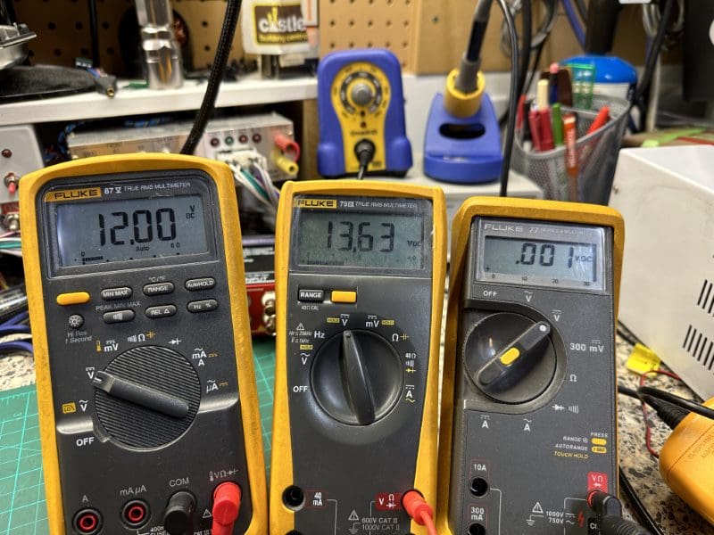
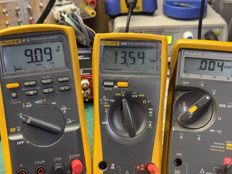
Let’s turn the amp up a bit. I increased the input signal until the amp was getting 12.00 volts. At this point, it was producing 40.71 microvolts of output or 0.435 picowatt of power. That’s like 0.000000000435 watt. I increased the output again until the amp saw 10.99 volts (the closest I could get to 11.0), and the power output was 0.6118 picowatt. Not what I’d call loud. Let’s turn it up, so the amp sees 10 volts (actually, 9.96V). We are at about 3 amps of current going into the amplifier and 0.716 picowatt of power going to the load resistor bank. OK, I increased the input signal again to try to get the amp input voltage down to 9 volts. The amp was drawing around 4 amps of current and producing 1.328 picowatts of power. The amp wouldn’t produce any more power as I turned up the input. Clearly, Rockford Fosgate has some low-voltage protection circuitry included in the design.
To put 1.328 picowatts of power into perspective, that’s how much power it would take for a speaker with a 90 dB 1W/1M efficiency rating to produce 1.23 dB of output. So, if you were really close to the speaker in a very quiet room, you might be able to hear it. It’s just a bit louder than the sound of a flying mosquito from 3 meters away.
But Wait, There’s More!
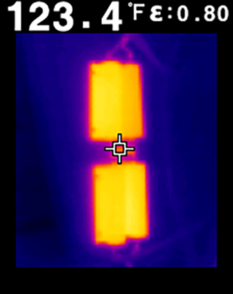
Ohm’s law rests for no man! While it’s a great tool for understanding voltage drops, it can also tell us a lot about how much power is being produced in a circuit. We’ll skip the math lesson right now and consider that we have about 4.5 volts being produced across the resistors while about 4 amps of current are flowing through them. This works out to about 18 watts of power. This doesn’t sound like much. Well, the resistors reached over 123 degrees F during the four or five minutes it took me to do this test.
Poor ground connections can get very hot very quickly, especially when there is a lot of current flowing.
Do You Think a 1-Ohm Ground Would Work?
So, would a car stereo amplifier or receiver work well if there were an ohm of resistance in the ground path back to the battery? We couldn’t get nanowatt or a milliwatt of output from a high-quality amplifier with 1 ohm of resistance added to the ground wire. Even if there were 0.1 ohm, you’d be in trouble at about 35 amps of current. To have any hope of an amplifier operating efficiently and reliably, the ground return path needs to have less than about 0.01 ohm of resistance with a 1,000-watt amplifier. Your digital multimeter can’t measure that value accurately.
So, how do you know if your ground connection is acceptable? Check out my article on testing wire size. This practical test will tell you whether you need to upgrade the power or ground wire in your audio (or lighting, winching, two-way communication, fuel pump, cooling fan, ignition or charging) system. Remote car starters and data interfaces also don’t like poor ground connections. Of course, if you choose a genuinely professional mobile enhancement retailer to work on your vehicle, they can handle everything for you. If you hear someone say that 1 ohm of resistance on an amplifier ground connection is adequate, send them a link to this article.
