Unless you have formal education in how alternating current waveforms interact with capacitors and inductors, it’s not illogical to assume that passive crossovers waste power from your car audio amplifier. These passive devices reduce the amplifier’s power production rather than converting it into heat. Let’s bust this myth about passive crossovers wasting amplifier power.
How Do Capacitors and Inductors Work?
If you measure the resistance of an inductor with a high-quality meter, you’ll find it has significantly less than 1 ohm of resistance. This isn’t the same as measuring its impedance. Impedance is the opposition to the flow of alternating current, whereas resistance is the opposition to the flow of direct current. Multimeters only measure resistance.
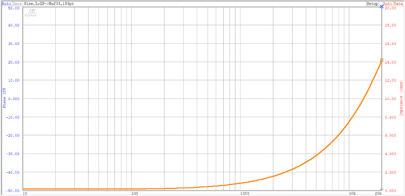
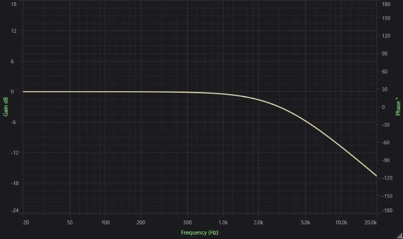
Let’s look at an inductor in some detail. I have a 0.21-millihenry air-core inductor in my slowly decaying collection of passive crossover components. If I measure the resistance of the inductor with my multimeter, I get a reading of 0.3 ohm. Keep in mind that the meter shows a reading of 0.2 ohm with the test leads shorted. So let’s take this inductor into my lab and measure its impedance characteristics. The chart below shows the inductive reactance of the inductor at frequencies from 20 Hz to 20 kHz.
Let’s wire the inductor in series with a woofer and look at the resulting impedance curve.
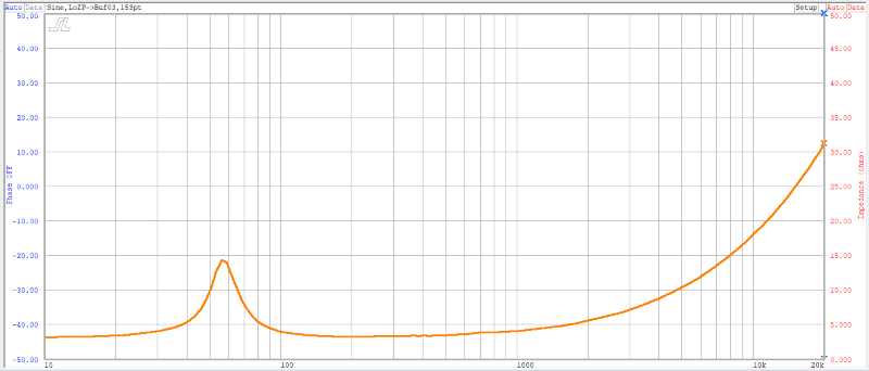
Power is calculated by multiplying voltage by current. The inductor adds opposition to current flow at higher frequencies. With less current flow, the amplifier produces less power for a given output voltage.
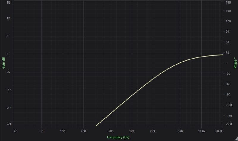
Let’s look at a capacitor. Unlike an inductor, capacitors block DC current, and their opposition to alternating current flow is highest at low frequencies. The chart below looks at the reactive capacitance of an 8.2-microfarad capacitor. Look at the range above 100 Hz. Below that frequency, my impedance meter wasn’t reading linearly.
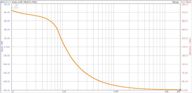
In simple terms, capacitors and inductors oppose alternating current flow at low and high frequencies. This increase in impedance causes less current to flow from the amplifier and reduces the system’s output.
Measuring Speaker Response with and without Passive Crossovers
Let’s cut to the chase, shall we? I have this 6.5-inch speaker set up in my test lab. I’ve placed the microphone a few millimeters from the cone so that the reflections and resonances in the room don’t affect the measurement. I’ll do three tests. The first will be the driver connected directly to the amplifier. The second will be with the 8.2-microfarad capacitor wired in series as a high-pass filter. The third will have the 0.21-millihenry inductor wired in series as a low-pass filter.
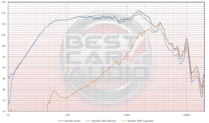
If you read our recent article about inductors not acting like a filter on a driver with rising self-inductance, you can see that effect here. The blue trace is down from the black reference trace by just a hair over 1 dB at 2 kHz and 3dB at 10 kHz. This response curve doesn’t match the intended -6 dB per octave attenuation we’d expect from a passive low-pass filter. Through the passband, the output of the unfiltered driver is within a decibel of the unfiltered signal. You can’t hear that, and it’s barely measurable.
Interestingly, the woofer’s output with the capacitor is identical to that of the unfiltered driver from 3.5 to 6 kilohertz, then gently attenuates to a maximum of -2 dB. Once again, it’s unlikely you’d hear that difference.
Passive Crossovers Don’t Waste Amplifier Power
Wasting power and causing an amplifier to produce less power are two entirely different concepts. Resistors waste energy. More specifically, they convert moving electrons into heat. This is why resistors have power ratings in watts – they get hot! An inductor or capacitor resists the flow of alternating current signals. Inductors create magnetic fields in the windings. Once created, the fields don’t like to collapse. Magnetic fields that change slowly, like those related to low-frequency audio information, aren’t affected significantly by the inductor. Conversely, high-frequency, fast-changing magnetic fields are met with opposition called inductive reactance.
Capacitors establish electrical fields between two conductive plates separated by a non-conductive dielectric. As mentioned, capacitors block DC current. You can apply a capacitor across a battery; it will simply charge to the voltage potential of the battery. In an audio circuit, faster-moving (i.e., higher frequency) waveforms can pass through the capacitor. Where inductors don’t like to change current flow direction, capacitors resist voltage changes. The faster-moving high-frequency information can pass through the capacitor, whereas slow-moving low-frequency information is met with opposition called capacitive reactance.
In both cases, these are magnetic and electric field oppositions to changes in current flow. As such, the energy is blocked but not converted to another state as we’d find in a resistor.
Do Passive Speaker Crossovers Waste Amplifier Power?
So, do passive crossovers waste amplifier power? The answer is simple: No. They might attenuate the output of a speaker by a decibel or two on the non-filtered side of the crossover point, but that is a result of an increase in reactance that reduces the current flowing from the amplifier to the speaker. If you need absolutely every decibel of sound energy from your speakers, an active amplifier configuration with a digital signal processor is the best source. A DSP also gives your installer complete flexibility in selecting and changing filtering frequencies.
Designing a premium car audio system that incorporates high-quality speakers with application-specific passive crossovers can sound stunning. Drop by a local specialty mobile enhancement retailer and audition some options for your vehicle today.
