I vividly remember the day I walked into work at a local car stereo shop, and the owner had mounted a 3-foot long Coustic AMP-560 amplifier to the front of the sales counter. Back then, bigger was indeed better. I think, at the time, we referred to that amp as a surfboard or maybe a skateboard – hard to remember; it was more than 30 years ago. We also had one of the 27.6-inch-long Rockford Fosgate Power 1000 amps in the install bay, ready to go into a client’s Chevy S10 pickup truck. While these weren’t the largest car audio amplifiers in history, their size told a story and commanded respect.
Fast forward three and a half decades, and almost nobody blinks when you tell them your car stereo has 1,000 watts of power. Nobody takes notice until you claim something over 5,000 watts. The guys who are serious about SPL competitions regularly install 10, 20 and even 40 thousand watts’ worth of amplification into their vans and trucks. Yes, tens of thousands of watts. No, I’m not kidding.

Sources of Heat in a Car Audio Amplifier
When it comes to amplifier development, managing the heat created by the components in an amplifier is a crucial part of the design. Well, I should say, it “should be” an essential part of the design. Unfortunately, however, it’s something many brands seem to ignore. So let’s talk about where this heat comes from.
The power supply and output devices in your car audio amplifier appear to work like light switches, but a better analogy would be that they are like a faucet or tap. If you open them a tiny bit, a little current flows. If you open them more, more flows. If you have some electronics background, you can think of them as a variable resistor or a variable voltage divider.
The problem with any resistive device through which current flows is that energy is wasted as heat. Power, defined in terms of resistance and current flow, is calculated by taking the square of the current and multiplying it by the resistance. If 4 amps of current are flowing through a 4-ohm resistor, 64 watts of heat is created in that resistor. Up the current to 5 amps, the power is now 100 watts. Think about how hot a 100-watt incandescent lightbulb gets after a few minutes of being illuminated. You can’t touch it without getting burned.
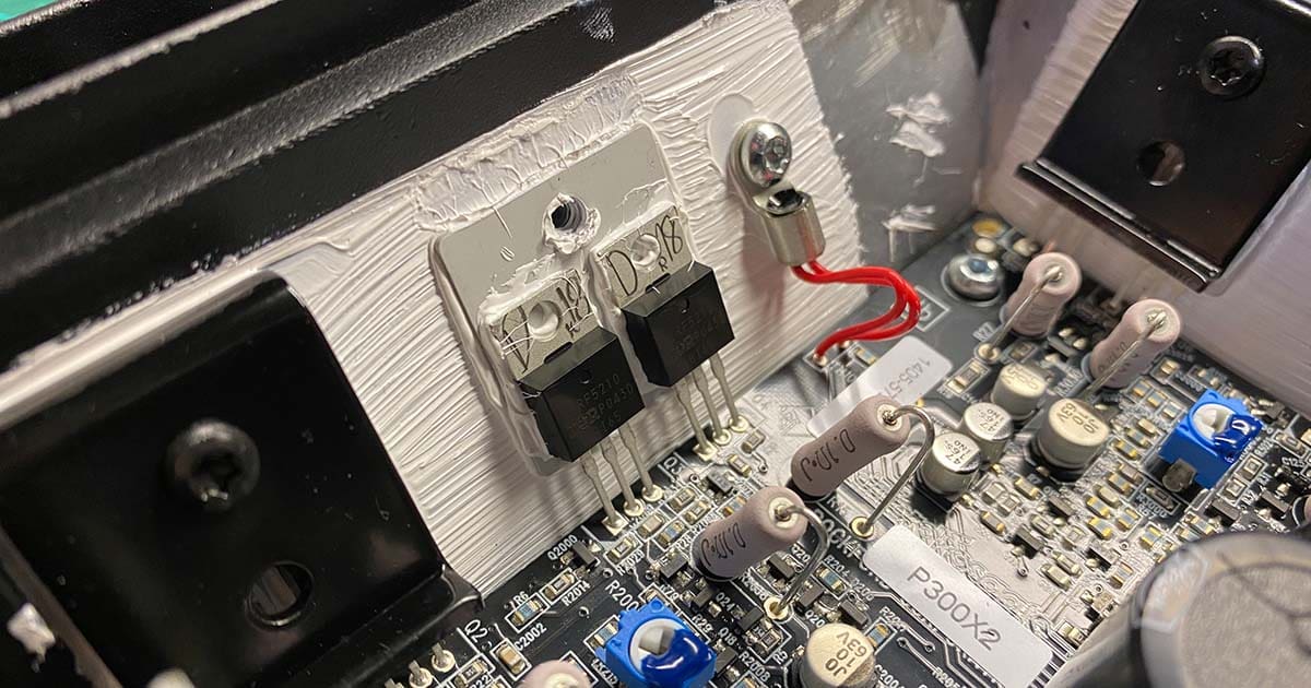
The power supply stage of a car audio amplifier typically uses MOSFETS that switch at very high frequencies to create a square wave that’s passed through the transformer. The transformer increases the voltage, then capacitors and diodes regulate (smooth) that voltage to produce the positive and negative rail voltages that will be used to feed the output devices. In a typical consumer-sized amp, we might see four, six or eight MOSFETS. If one of these devices is rated to pass 10 amps of current and has a minimum resistance of 0.22 ohm, 22 watts of heat can be created. A typical MOSFET has a footprint of 0.5 to 1 square inch. That’s a LOT of heat in a small package. If we have eight of these in an amplifier, working as hard as they can, that’s 176 watts of heat wasted with 80 amps of current flowing into the amp. We haven’t even looked at the output stage, which will create more heat.
These power supply switching devices need to be attached to a heat sink to keep them cool. More accurately, the heat sink draws heat away from the devices and hopefully dissipates it into the surrounding air.
So, why can’t we just let these MOSFETs get hot? Well, resistance increases as temperature increases. If our devices have a minimum resistance of 0.22 ohms at room temperature, that value might increase by 50% when the temperature reaches 167 degrees Fahrenheit (75 degrees Celsius). Think back to how power is calculated – the square of the current multiplied by the resistance. At 167 F, each device passing 10 amps of current would create 33 watts of heat, and the group would be wasting 330 watts of energy. How fast do you think the heat sink will increase in temperature? More heat means more resistance, which wastes more power, which produces more heat. It’s a dangerous cycle that can quickly cause switching devices to be permanently damaged or fail completely.
Amplifier designers who know what they’re doing work hard to choose switching devices with the lowest possible resistance. They include enough of them to ensure that the amp won’t overheat too quickly, even at full power. I chose the words “too quickly” specifically over “ever” because almost all car audio amps can be pushed to the point that they overheat. If you wanted something foolproof or overheating-proof, the amp would need a colossal heat sink and would have to include many fans. Even then, if the amp is in the trunk of your car, all the air in the compartment would eventually start to heat up as well. Have you ever seen the air-conditioning systems required to keep a computer server room cool? Companies like Amazon spend millions of dollars cooling their server farms each year.
Car Audio Amplifier Cooling Methods
There are two ways to draw heat away from the switching devices in a car audio amplifier: a high-mass heat sink or forced-air cooling. Each has its benefits and drawbacks, of course.
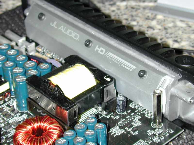
In a high-mass heat sink, typically the devices are affixed to a large extruded or cast aluminum mass. White thermal paste is applied to the devices to eliminate air gaps between the bottom of the devices and the aluminum extrusion to increase heat transfer. How the devices are clamped to the heat sink plays a role in heat transfer. Some companies use heavy-gauge spring-steel clips, while others use metal plates or bars to hold things in place. I’ve seen some amplifiers use finned aluminum extrusions as hold-down devices to improve heat dissipation further.
The large mass of the aluminum heat sink can absorb a lot of thermal energy before it gets too hot. And the amplifier (hopefully) protects itself. Many of these designs have cooling fins built into them to increase the total surface area and allow heat energy to dissipate into the air.
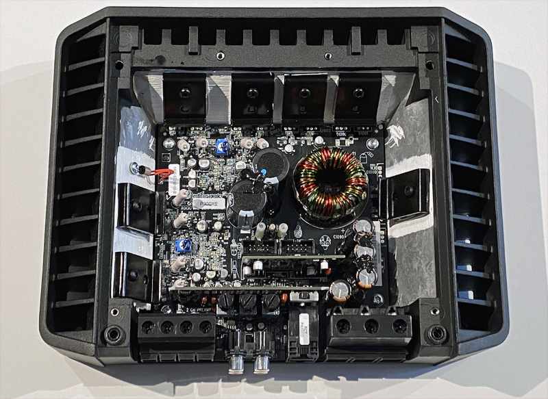
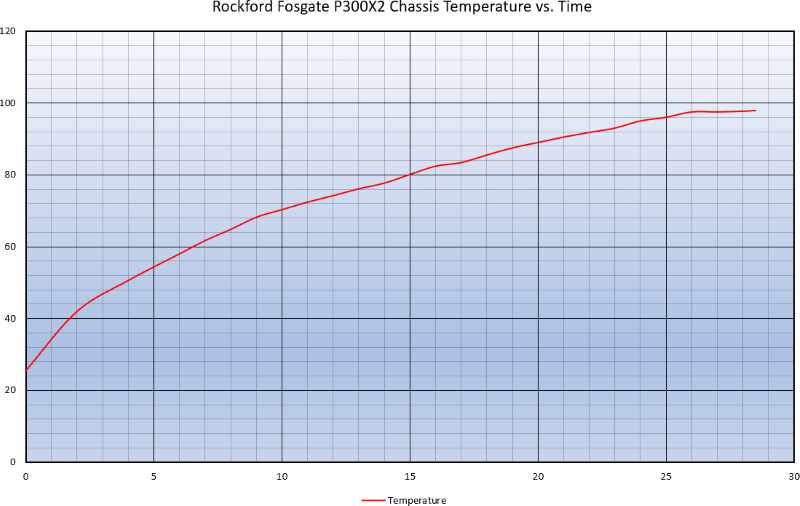
The Rockford Fosgate amp shown above was recently put through its paces on the BestCarAudio.com test bench for a Test Drive Review. As part of my testing, I always check to see how long an amp will run at full power before the thermal protection circuit shuts it down.
In the case of the P300X2, it ran for 28.5 minutes while producing 360 watts of power. The amp is only rated for 300 watts, but it dramatically exceeded its published ratings, as is usual for Rockford Fosgate products.
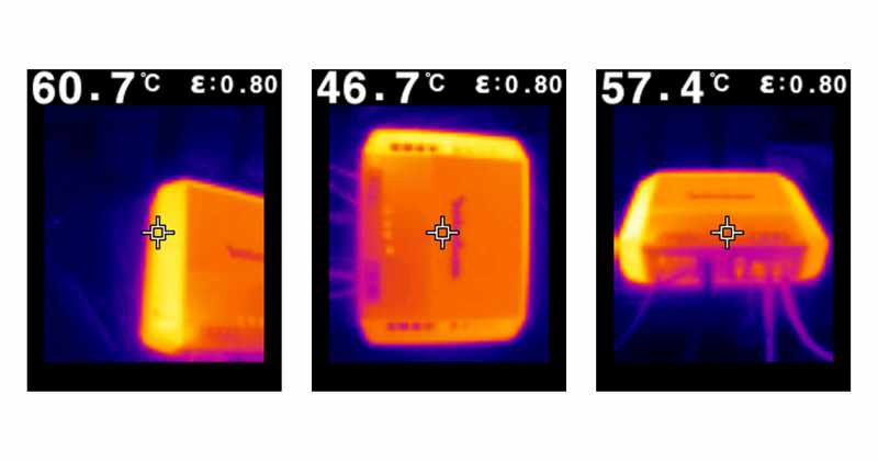
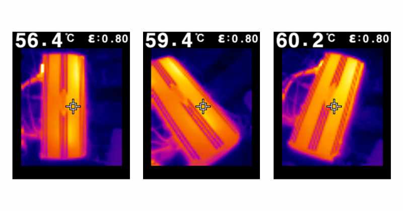
I took a few thermal images of the amp while it was being abused on my test bench. As you can see, the majority of the heat it produced came from the MOSFETs used in the power supply on the left side of the chassis. The amp shut down at an external temperature of 203 degrees Fahrenheit (95 degrees Celsius).
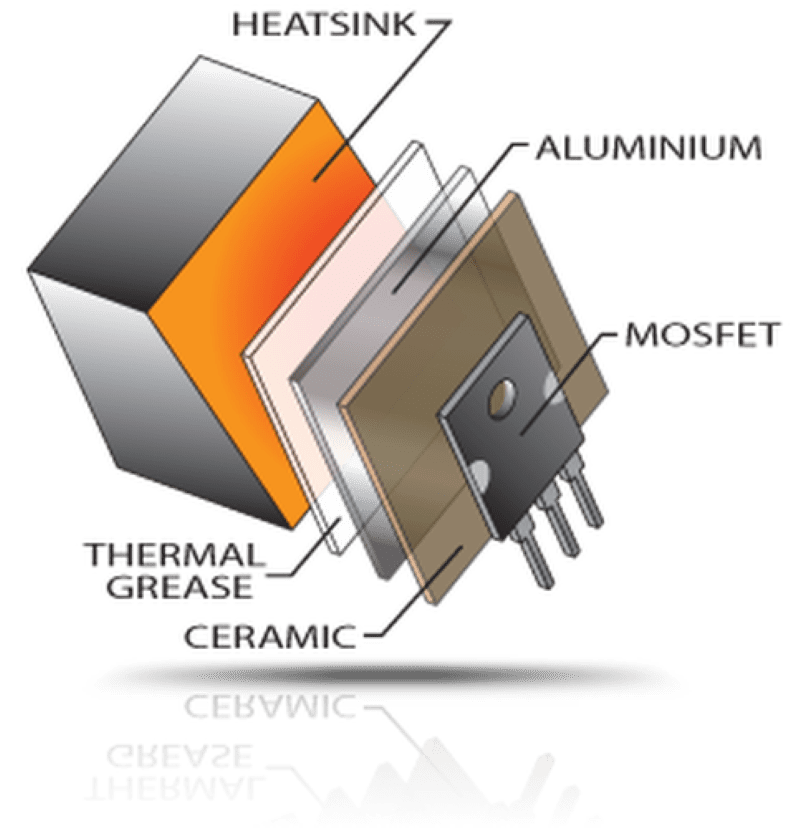
Rockford Fosgate has invested a significant amount of time into optimizing the cooling capabilities of its heat sinks. The Punch Series P300X2 I reviewed includes the Maximum Efficiency Heat Sink Application 3 (MEHSA3) design that adds a layer of aluminum to the underside of the switching devices. This plate increases the surface area contacting the heat sink to increase the heat transfer rate.
Forced-Air Cooling
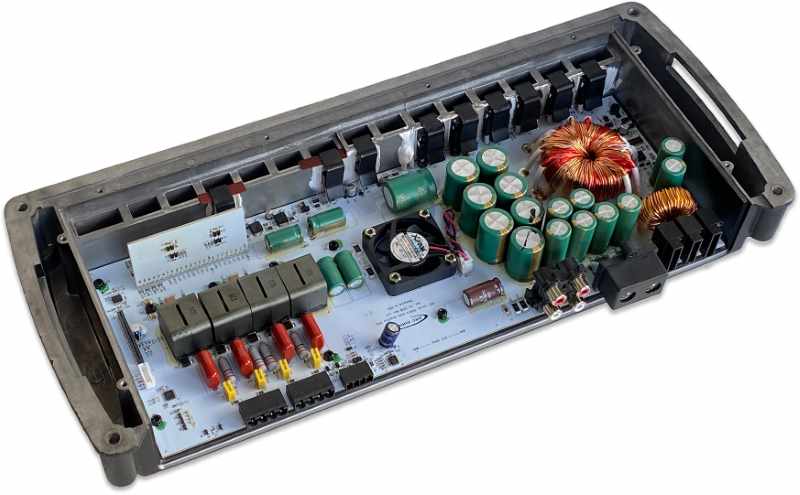
The second way of keeping the switching and output devices cool is to use a heat sink in conjunction with a fan. As the fan draws air over the heat sink, heat is transferred away, just as it would be with the radiator of a car or truck. The advantage of using fan cooling is that the heat sink can be smaller and lighter, reducing the cost of the amplifier chassis. However, as with seemingly everything, there is a drawback. Fans can make noise if not integrated properly. Companies like ARC Audio use the microcontroller that controls the operation of their amplifiers to control the fan. The cooling fans run at very low speeds when the amp initially turns on. If the heat sink starts to get hot, the fan speeds up automatically and runs until things are cool again. Your music is likely playing at a respectably high volume level when the fans are at full speed so that you won’t hear them.
Optimizing fan-cooled designs does take some thought. I’ve tested many amplifiers with simple C-shaped aluminum extrusions with a fan in the bottom or side of the amp and vents on the other side. Fans blowing air through the middle of the chassis do very little to draw heat away from the amp. ARC Audio dedicates serious thought to its cooling designs. In most solutions, the fan is located centrally in the middle of the amp, on the circuit board. The fan draws air into the amp from the sides, then expels it through a channel between the board and the heat sink and out the ends. This channel is typically lined with cooling fins to dramatically increase surface area. The result is amplifiers that run cool and don’t produce a mechanical racket when you turn them on. Unless it’s for competition-level SPL applications, you don’t want to select a fan-cooled amp where they run at full speed all the time.
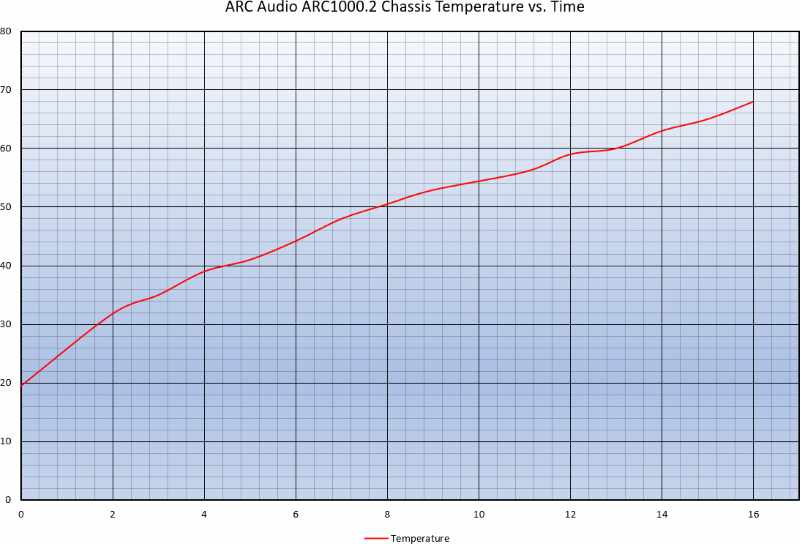
I have an ARC Audio ARC1000.2 two-channel amp here in the lab. I set it up on my bench and drove it at an output level of 1,000 watts into a pair of 2-ohm loads. Just as with the Rockford Fosgate amp, I monitored the temperature of the chassis for the test duration.
As you can see, the ARC1000.2 ran for 16 minutes while producing 1,000 watts of power. While 16 minutes doesn’t seem like a long time, there are a few things to consider. First, these tests are a worst-case scenario with steady-state test tones, not music. Even the most bass-heavy tracks are likely only to draw 40% or 50% of the amplifier’s maximum power capabilities if you average the output over time. If you’re thinking, “Wow, the Rockford Fosgate Amp ran for longer,” you’re right, but it was only producing 1/3 as much power, so it didn’t have anywhere as much heat to dissipate. As such, this isn’t intended as an apples-to-apples comparison; it’s just two examples.
The cooling fan in the ARC1000 amplifiers is buried deep in the center and attached to the main circuit board. A microcontroller determines its speed.
When Thermal Management Isn’t Considered
Let’s look at two examples of amplifiers that are more generic in terms of their thermal management. Up first, I have a subwoofer amp from a German company. It’s rated to make just over 1,000 watts, but only made 663 watts at 1% THD+N. The efficiency of this amp is terrible at under 60% into a 1-ohm load. This means it’s going to get hot, fast. I put the amp through the thermal testing process at an output of about 940 watts – closer to its rated output capabilities. The right rear corner of the heat sink started getting hot very quickly. At the two-minute mark, the amp shut down, and the heat sink was at 171 degrees Fahrenheit (77 degrees Celsius). Yep, 120 seconds is all it lasted.
The next amp is from Brazil. This amp claims to be capable of producing 3,000 watts of power. I measured just a hair under 1,800 watts on my D’Amore Engineering AMM-1. Keep in mind; this isn’t a CTA-2006-C compliant measurement. The Clip Light on the multimeter indicates a level where signal clipping is significant. As such, it’s not a comparable measurement to products like ARC Audio or Rockford Fosgate. This amp is relatively small and has a fan that blows air through the chassis center. As I mentioned above, this design doesn’t do much to keep the internal components cool. Based on my observations, I didn’t expect much in terms of thermal stability, and as often happens, my prediction was correct. In just under four minutes at an output level of 1,100 watts (which correlated to a current supply level that was consistent and stable from my power supply at the time), the heat sink of this amp reached 205 degrees Fahrenheit (96 degrees Celsius), and it shut down. At higher power levels, the playtime would be shorter. If you ever think to yourself, “Wow, this is a lot of power from a small chassis and not a lot of money,” when buying an amp, think about what’s missing – heat sink mass or cooling tech.
Why Does Heat Sink Temperature Matter So Much?
Small electronic devices like transistors, MOSFETS and even integrated circuits have tiny active components inside them. For example, the silicon component in a typical TO-220-case MOSFET might be 0.2 by 0.2 inch on the high end. As it turns out, most of the device’s size is a heat sink. When things get hot, they expand in size. When they cool, they shrink. Extreme thermal cycles can wreak havoc on components, eventually leading to minute cracking that can reduce their ability to expel heat energy. From another perspective, the thermal paste used to help conduct heat from a transistor or MOSFET to the heat sink will eventually dry out. This drying process is accelerated by heat. Once the paste is dry, it doesn’t conduct well, and the devices may overheat and fail.
As we stated at the beginning, resistance increases with heat. Therefore, as your amp gets hotter, its efficiency will decrease. This reduced efficiency accelerates the vicious and potentially destructive heating process.
In short, if you want your investment in a car audio amplifier to last, choose a solution that manages heat appropriately. Small amplifiers might be convenient in terms of installation options, but their size limits their ability to extract heat from the devices and maintain efficiency. So, aside from choosing products that sound great, keep thermal management in mind. Your local specialty mobile enhancement retailer can help you select a solution that will perform well in your application.
