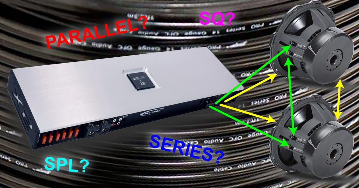
Have you ever measured or tested something and not fully believed the results? A while back, I wrote an article that looked at the different options for wiring a pair of dual voice coil subwoofers to a single amplifier. The options are to wire the voice coils in each subwoofer in series the woofers in parallel, or wire the coils in parallel and the subwoofers in series.
The outcome of the mathematical analysis said that we should wire the coils in series and the woofers in parallel. In my head, I didn’t think the results would have differed. I figured it was like saying 10+4-4 isn’t the same as 10-4+4. When you doubt your results, the best thing you can do is revisit the experiment. Let’s do a real-world acoustic test with a pair of dual-voice coil subwoofers to see what happens regarding output and frequency response.
Should Subwoofer Wiring Schemes Matter?
In the simplest of terms, a dual voice coil subwoofer is like a pair of resistors. In the case of our subwoofers, they are 4-ohm resistors. Because we have two drivers, we have a total of four resistors. If you understand Ohm’s Law and the basics of series and parallel wiring, it shouldn’t matter how we arrange these resistors in terms of the net load presented to the amplifier.
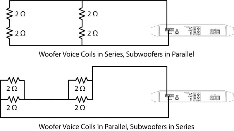
In terms of keeping things simple, it’s easiest to wire the voice coils on each subwoofer in series, then connect both drivers to our amplifier in a parallel configuration. That would look like the image below.
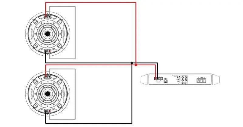
Since most subwoofer amplifiers have two positive and two negative connections, we can just run a set of wires to each subwoofer, thereby reducing the resistance in the wiring as much as possible.
The drawback to this wiring scheme is that one woofer will continue to get power if the other fails. In that scenario, the enclosure design is no longer suitable to control the motion of the subwoofer that is still playing and could be damaged. To ensure that the drivers are protected in the event they might be abused, it’s better to wire the coils in parallel and the subwoofer in series. This is called “failure mode analysis” in automotive engineering and other disciplines.
Speakers Don’t Behave Like Resistors
We need to worry about reactive impedance rather than just resistance in the real world. For example, voice coils in subwoofers are highly inductive, and how we wire the drivers might affect their performance. In that previous article, we saw that the inductance didn’t change, but the Q was lower, as was the net impedance with the driver coils in series and the subwoofers in parallel. The question is, how much does it matter? Maybe one configuration is better for sound quality, while the other might be better for those who want their music to play as loudly as possible. We’re about to find out.
Subwoofer Wiring Measurement
The test enclosure for this experiment is on loan from Lee Mattason at Burlington Radioactive. It’s a sizeable bass-reflex enclosure with a net internal volume of about 4 cubic feet and includes a slot vent tuned to 35 hertz. I mounted the drivers in the enclosure and ran speaker wires from each of the voice coils out so I could easily change how they were wired. To keep things simple, I used what’s called a ground-plane measurement to compare the response of the two wiring options. In a standard application, this would be performed in a large anechoic chamber or outdoors. Since it’s below freezing and there are a few inches of snow on the ground, I did the test in my listening room. I also placed the microphone one meter from the enclosure. As such, the SPL measurements will be 6 dB higher than with a standard test. In terms of drive level, I used my test amp to feed 1 volt to the drivers as measured at 60 Hz with a Fluke True RMS multimeter. I performed three sweeps for each wiring configuration.
With the voice coils on each subwoofer wired in parallel and the woofers in series, here are the unsmoothed measurements.
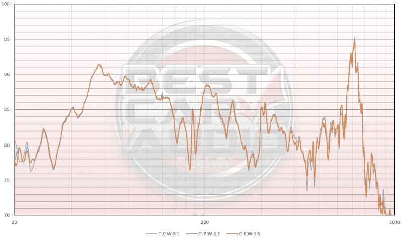
Aside from some background noise below 25 Hz, the measurements of the output of the three sweeps are almost identical. There are a few small variations of less than 1 dB, but they are insignificant.
Next, I rewired the subwoofers so that the voice coils on each subwoofer were in series; then, I wired each subwoofer in parallel with the amplifier.
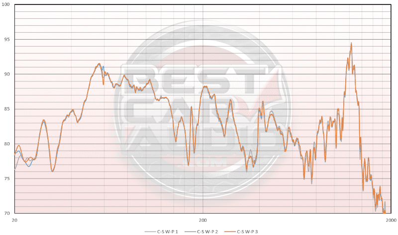
Once again, the measurements were statistically identical, aside from the noise below 25 Hz. Happy with the data, I averaged the three measurements for each wiring configuration and plotted those values on the same chart to see if there was a difference.
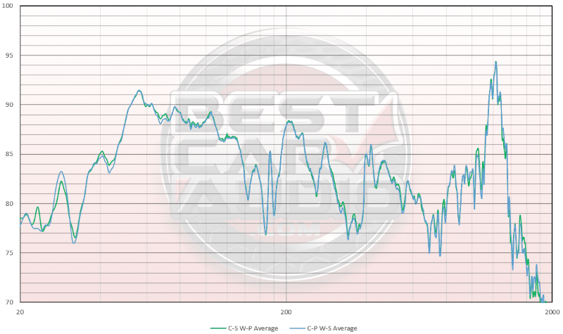
The short answer is that it doesn’t matter how they’re wired. If I had to pick one option, having the coils in series and the woofers wired in parallel might yield a 0.5 dB SPL increase at a few frequencies. Overall, as I had hypothesized, the results are so close that it just doesn’t matter. You could never tell the difference between the two by listening.
How Should Your Installer Wire Your DVC Subwoofers?
Knowing that the two wiring schemes produce effectively identical results, other considerations become more important in choosing the best way for your installer to wire your car audio subwoofers. If you want to ensure that as much power as possible is transferred from the amplifier to each subwoofer, wire the voice coils in series and have them run a wire from each driver to the amplifier. If you’re concerned that you might harm a subwoofer by overpowering it and want to protect the other driver from physical damage, then have your installer wire the voice coils on each driver in parallel and wire the subwoofers in series. If one subwoofer fails, the other will stop working, and you’ll know that you’ve done something wrong.
Drop by a local specialty mobile enhancement retailer today if you need help choosing the best subwoofers for your car audio system. Tell them the guys at BestCarAudio.com sent you!
